 deftcoyote
BACKGROUND
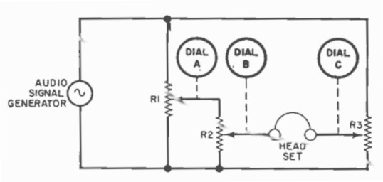
The simple analog computer is essentially a comparator circuit where balancing the circuit gives you an approximate answer to several mathematical functions. It functions similar to a slide rule. I don't know what the earliest version of this is, but they were common in the late 50s and early 60s as kits.
The ones I am aware of:
- 1958 - Mr. Math in June issue of Radio Electronics (https://worldradiohistory.com/Archive-Radio-Electronics/50s/1958/Radio-Electronics-1958-06.pdf)
- 1959 - Calculo Analog Computer Kit (http://www.ccapitalia.net/descarga/docs/1959-calculo-analog-computer.pdf)
- 1960 - Edmund Analog Computer (https://computarium.lcd.lu/photos/albums/EDMUND_ANALOG_COMPUTER/album/index.html)
- 1961 - General Electric Project 4 Computer (EF-140) (http://www.ccapitalia.net/descarga/docs/1961-general-electric-EF-140.pdf)
- 1962 - American Basic Science Club Analog Computer (https://t-lcarchive.org/american-basic-science-club-analog-computer/)
- 196? - Mac-1 Mini Analog Computer (http://www.vintage-icl-computers.com/icl48d)
- 1966 - Pot Computer in January issue of Electronics Illustrated (https://worldradiohistory.com/Archive-Electronics-Illustrated/Electronics-Illustrated-1966-01.pdf)
- 1969 - Science Fair Electronic Computer Kit (https://www.computerhistory.org/collections/catalog/X744.86A)
- 2008 - Calculatoria (http://www.nicolamarras.it/calcolatoria/calcolatrice_analogica_en.html)
- 2022 - Recent Makezine article (https://makezine.com/projects/electronics-fun-fundamentals-analog-reborn/)
- 2023 - VSAC - Very Simple Analog Computer (https://github.com/dl3hrt/VSAC-Very-Simple-Analog-Computer). Only an image is on github. It uses the overlapping dials like mine, and seems it will appear in a German magazine in March 2023.
In December of 1961, the Edmund Analog Computer and G.E. EF-140 were described in an overview of this type of circuit in an article in Popular Electronics (https://worldradiohistory.com/Archive-Poptronics/60s/61/Pop-1961-12.pdf).
More recently, similar instructions were given to explore this circuit as a school activity in https://schoolbag.info/science/laboratory/8.html. It was also recreated here: http://www.arthropodsystems.com/AnalogComputer/AnalogComputer1.html. The circuit was also implemented with high-precision potentiometers in 2008 as listed above.
I would be very interested in any other versions of this or more information about these. Specifically, more information about the Mac-1 and copies of the manual for the Edmund Analog Computer and the Science Fair one. Here's a summarized version of the Edmund manual in Czech (I think): http://dexovo.cz/analogove-vypocetnictvi-edmund-cast-i.php.
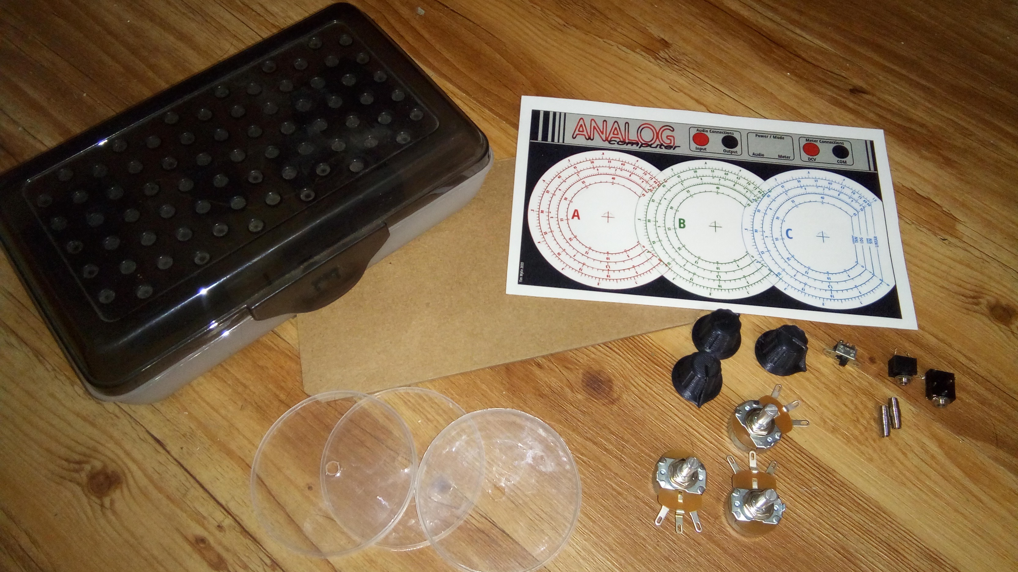
 I included in the files the gauge section without any numbers as well. This allows you to mark the gauges specific to your pots so that they're more accurate.
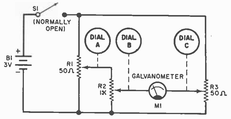


 Kelly Heaton
 MaBe42
 Marcelo
Love this. Question - is there a straightforward way to design (PhotoShop or other) custom dials. I.e. what is the process to create calibrated dials based on a start and end point (and interior angle) for a given pot?