 nqtronix
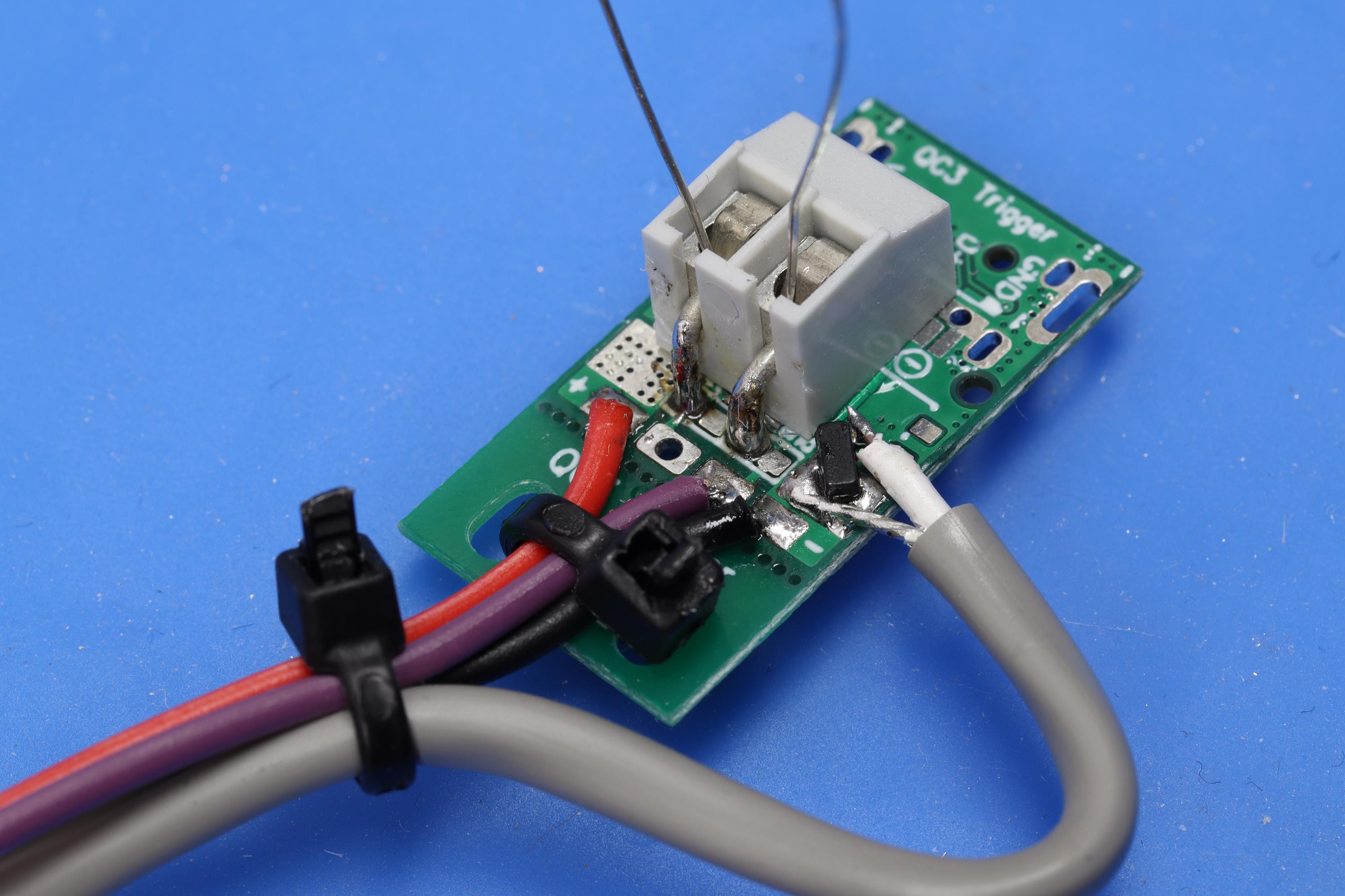
A small test PCB (from a yet unreleased project) is the DUT and contains an ATTINY13A, the reference resistor, a test resistor (screw mounted) and a a temperature sensor. Well, not a proper sensor, but a 3904 SMD transitor whose BE forward voltage changes at about -2.1mV/°C . Both the base and the collector are soldered to GND to improve heat transfer into the transistor. The voltage is measured with a multimeter. The calculated id value is send to the uart TX pin, received by a uart-usb adapter and displayed on terminal on my phone.
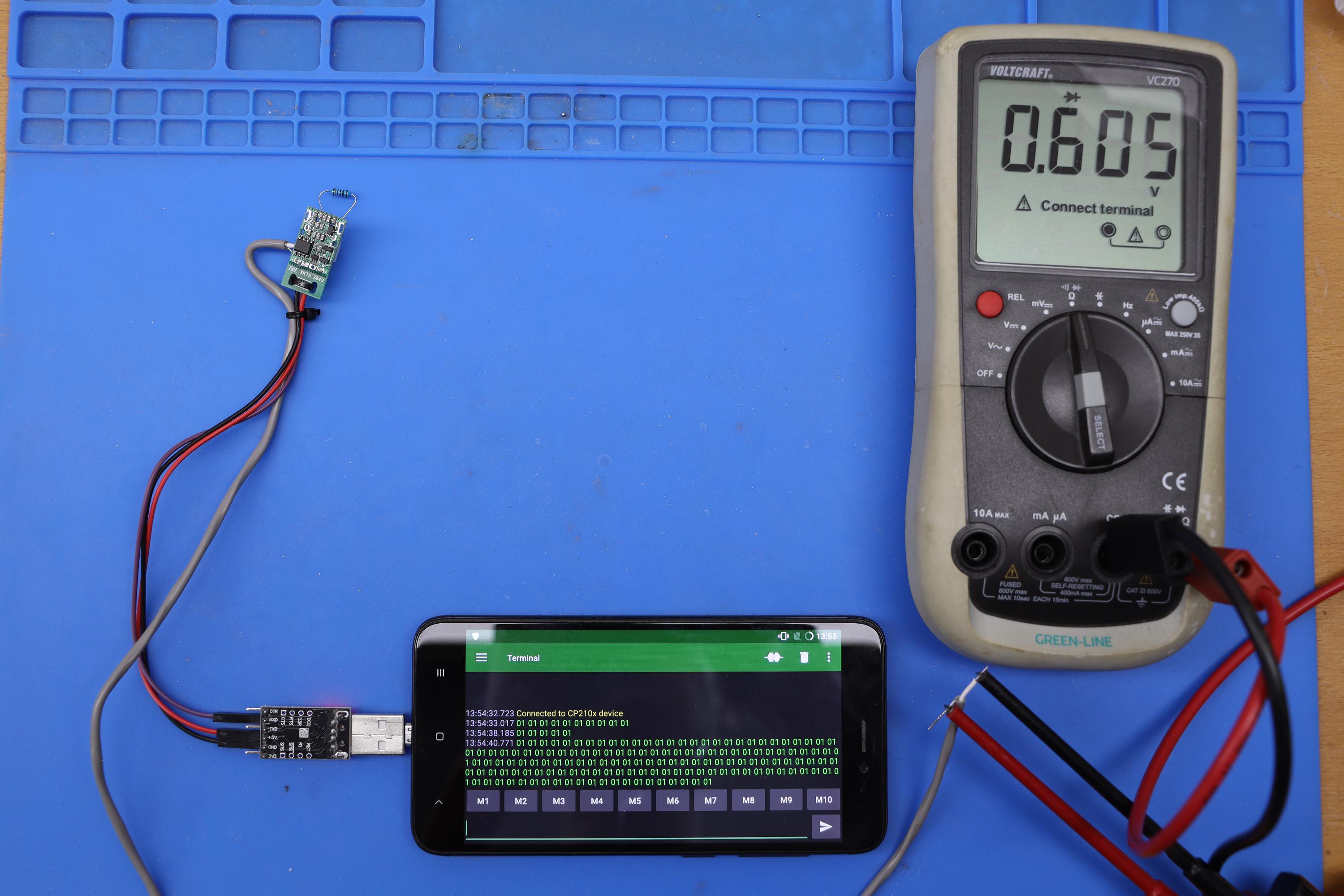
The test procedure is simple:
- Initialize the code at room temperature (in my lab 15°C = 0.64V)
- Connect a resistor to test
- Heat up the board with a hot air rework tool until the reported value is incorrect
I've measured three 1% resistors, all of them are edge cases with the worst expected performance:
- 1.0k (0x01): heated up until 0.35V (15°C + 138°C = 152°C) without a change in output value, than the MCU crashed. This is not surprising as it is only rated at up to 125°C. After a power cycle it worked again.
- 4.7k (0x05): heated up until 0.42V (15°C + 104°C = 119°C), then output value changed to 0x04.
- 1.0M (0x1E): heated up until 0.44V (15° + 95°C = 110°C), then output value changed to 0x1D.
Although this is not a precise test by any means, I'm very happy that the results exceeded my expectations. I'm confident that the code will work on most AVRs reasonably reliable until 70°C, maybe 85°C. For critical applications where an incorrect detection could lead to permanent damage I'd still recommend to only use the even values and interpret all odd ones as an error.
Discussions
Become a Hackaday.io Member
Create an account to leave a comment. Already have an account? Log In.