Michael Gardi
What It Is and What It's Not (Updated)
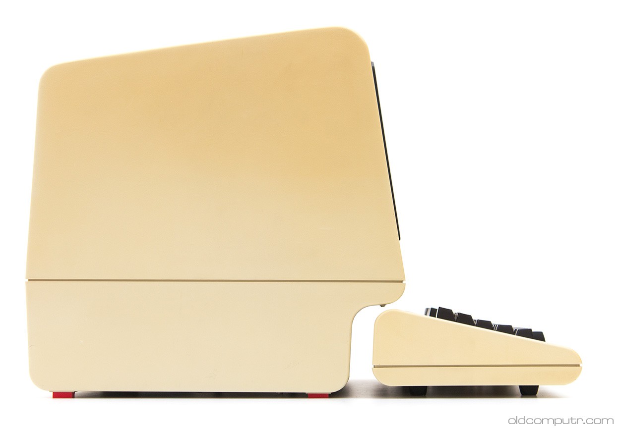
Since the DEC VT100 was the gold standard for serial terminals in the early years, that's what I will base my design on, and since it will be a driver for a 2:3 scale PDP-8I I'll scale my design accordingly.
I will not be making a true replica VT100. The plan in fact is not even to make a real serial terminal. I want to make something that is clearly a VT100 derivative as close as possible in look, but sourced with modern components. So for instance it will have an LCD screen disguised as a CRT, and the 2:3 scale precludes having a full sized keyboard with number pad like the original. The display will be hooked directly via HDMI to the Raspberry Pi running the PDP software, and the keyboard will be USB connected to the Pi as well.
May 27, 2021: The previous two paragraphs describe the project as originally conceived. As the project progressed I realized that there was so much more I could do with this reproduction. Near the end of this writeup you will see that I created a Mini Arcade version with joystick and buttons in lieu of a keyboard. Since the RetroPie software for the arcade was running on a Raspberry Pi anyway, and we did have a keyboard as well it's wasn't a big leap to see this VT100 reproduction as a small stand alone desktop machine.
My very last sentence in this writeup was "The one thing that I didn't do was create an actual RS-232 terminal. I don't have the bandwidth or a use case for this now, but based on projects like PiTERM, it looks like it would be pretty easy create a third variation that did just this." Well as part of this update I plan to correct this shortcoming. See the new sections at the bottom for details.
May 29, 2021: With the RS-232 hardware sorted I wanted to take one more step and achieve as authentic a VT-100 experience as I could. Thanks the the efforts of Lars Brinkhoff I was able to do just that. More details at the bottom.
I managed to find a VT101 Video Terminal User Guide online, and basically, for someone that often does reproductions of artifacts that they can't actually afford to buy, struck gold.
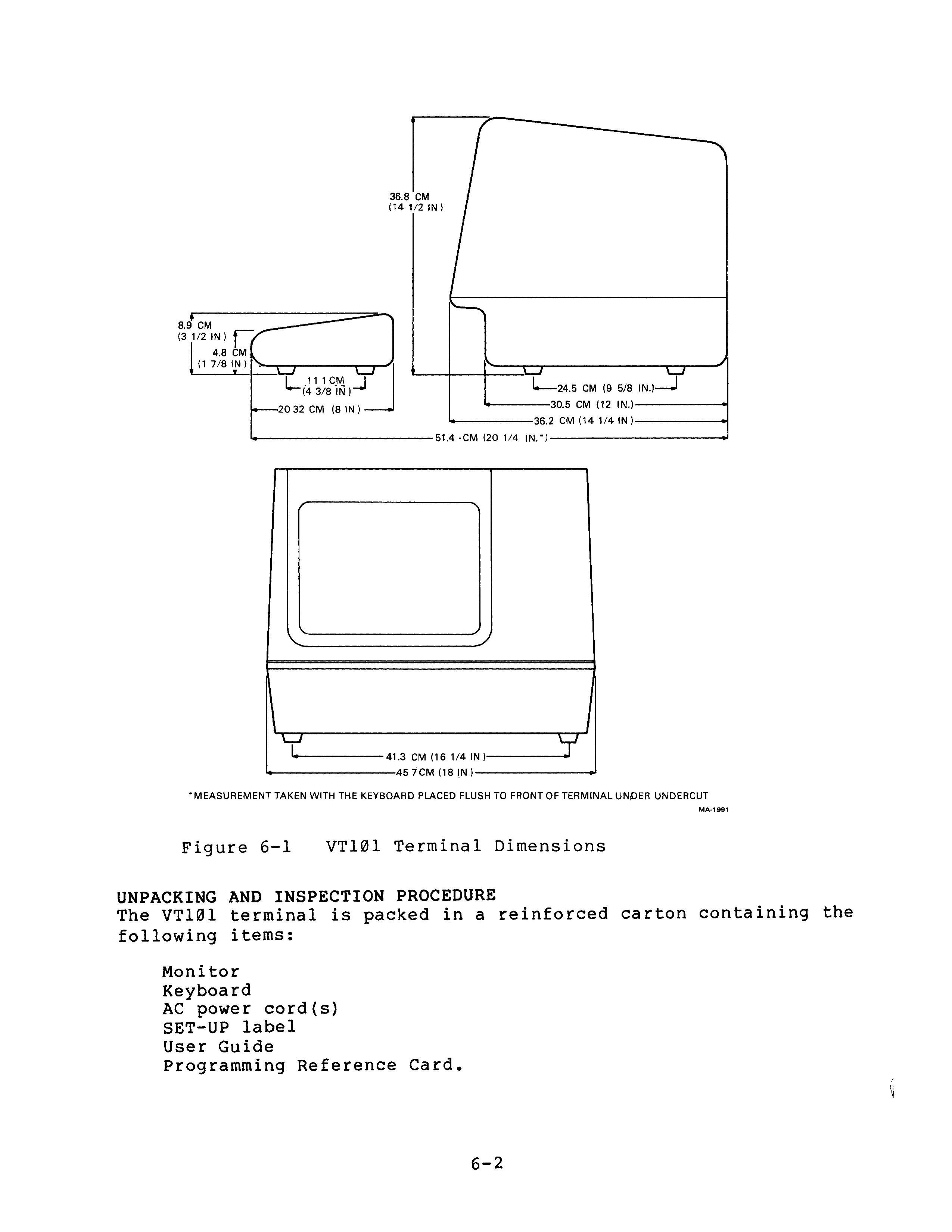
Figure 6-1 is all I need to create a suitably scaled VT100 3D model.
So just a couple of hundred hours of 3D printing (seriously the keyboard alone is 30+ hours or so), and shoehorn in a keyboard and display and I'll be done.
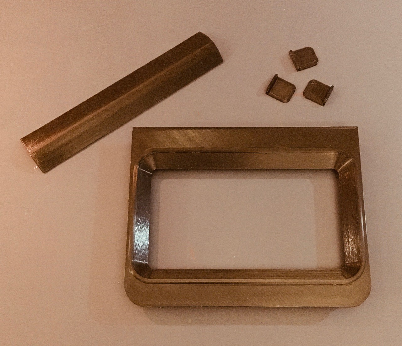
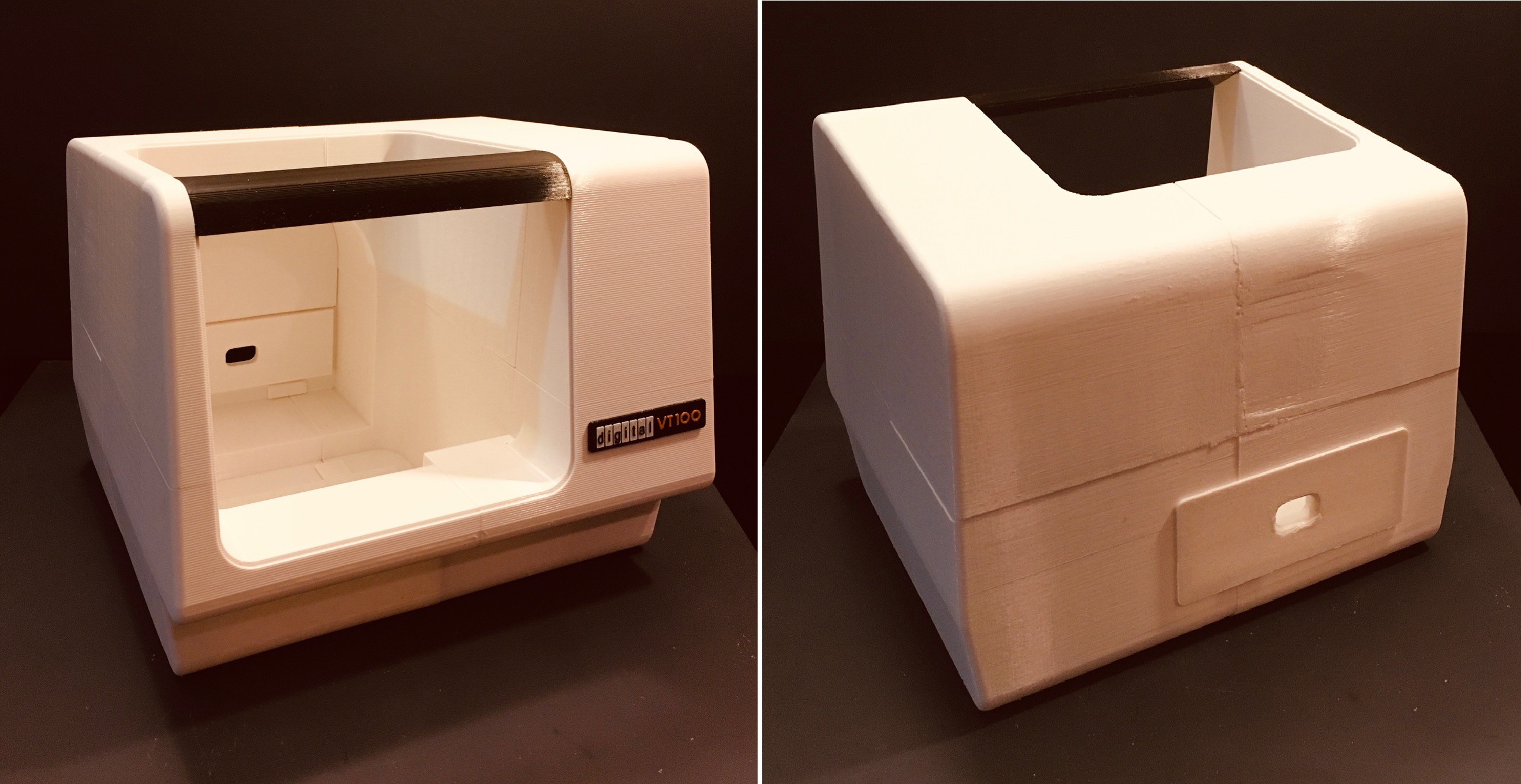
At a point where I had already printed about half of the terminal pieces I found this photo.
Notice the back of the terminal has a bend in it like the sides do, and unlike the drawing in Figure 6-1. Too late to adjust my design. Sigh, a small miss here.
Who Knew Keyboards Were Such a Big Thing?
Probably most of the people reading Hackaday knew, but not me. I think because I'm not a touch typist (long story), one keyboard is pretty much the same as another to me. That is certainly not the case for the large and vocal group of keyboard enthusiasts out there.
When I scaled down the keyboard frame and measured, I found that at most I had an area of 295 x 110 mm to fit the actual keyboard. Yikes! So I began my quest for the perfect keyboard for this project.
I have a couple of smallish Bluetooth keyboards around and thought something along those lines would do the trick, but after a pretty extensive search could find nothing suitable.
For a while I thought about creating a custom keyboard based on the SICK-68 design I found in these very pages. But that felt too much like a complete project inside of my project. So no.
After that it didn't take long before I stumbled upon the wild world of mechanical "gaming" keyboards. 40%, 45%, 60%, linear vs tactile, Cherry MX, ortholinear vs staggered, so much to learn. The good news for me was the many of these designs had a form factor small enough to fit into my VT100 keyboard frame.
Case in point, the Planck EZ is only 234 x 82 mm, well within the limits for my build. However the cost of this absolutely gorgeous piece of technology was prohibitive for this project, and the ortholinear layout not in keeping with the original VT100's. But I felt I was on the right track here.
Eventually I found the MOTOSPEED CK61.
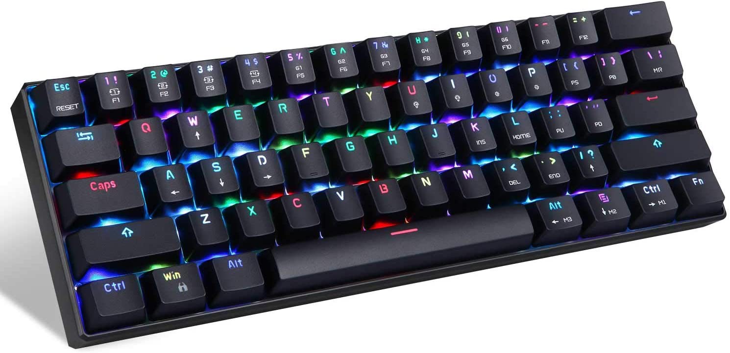
At 290 x 100 mm the CK61 just fit into my design. It was well reviewed and reasonably priced enough that I could afford to use it for this project. I ordered the version with the "Blue Switch" which I assumed were Cherry MX BLUE (or clones) and in fact turned out to be nice and "clicky". The more conventional staggered layout is definitely a better look for this reproduction. I knew that I would never find a keyboard with a number pad that would fit, so I feel that this keyboard is a reasonable choice.
And here is the result.
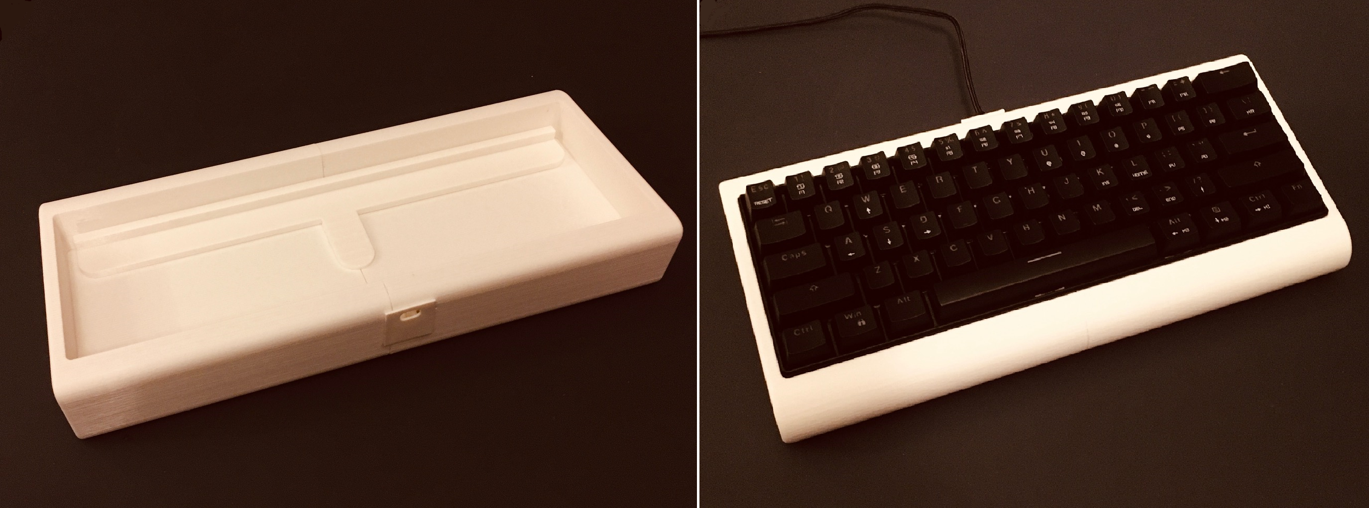
On the left is the VT100 keyboard frame. I had to print it in two pieces which I glued together and reinforced with the cross piece you can see, also glued on, which supports the front of the keyboard at the proper height. On the right the finished keyboard.
I'm happy with the result which is authentic looking enough for me. Until it was all together, I had not realized how uncomfortable some of these early keyboards must have been to use. Again as a hunt and peck guy I didn't notice back in the day when I'm sure that I used said keyboard at some point in my career.
The VT100 design is basically done. but even at 2:3 scale this is a still a pretty big artifact to 3D print. Because of the limited size of my print bed, I will have to split the console into 14-16 pieces, each of which will take 15-20 hours to print. So that leaves me with a lot of time on my hands to work on some of the other project details, like the Logo.
I had to print the Logo full size because at 2:3 scale the letters fell below the resolution of a .4 mm print nozzle. So it's ready to slap on when I get enough of the console printed and assembled.
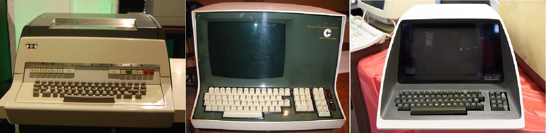
According to Wikipedia, the PDP-8/I was launched in 1968, while the VT100 wasn't available until August of 1978. While it is conceivable that an old PDP-8/I at some point was connected with a brand new VT100, it far more likely that early PDP-8/I's were connected to some brand of teletype machine like the Teletype Model 37. By 1970 early VDUs like the Datapoint 3300 or DEC's own VT05 (I love the Jetson's futuristic look) were probably used.
If anyone in the Hackaday community has actual first hand knowledge of terminal usage I would be very curious to know.
At any rate, I guess I get low marks for historical accuracy matching a VT100 with Oscar's PiDP-8/I reproduction. On the other hand, the DEC VT100 is probably one of the most iconic VDUs of all time, both in terms of its look, and the protocols (the emerging ANSI X3.64 standard) that it supported, to the point where VT100 emulators are ubiquitous even today.
Update
Jim Beatty was kind enough to share his experience with PDP-8 machines.
I cut my teeth on PDP-8s from about 1968-78. Early on an ASR-33 teletype was the terminal of choice, at 110 baud. Later there was a terminal called a Decwriter (I believe it was dot matrix). Video terminals were a rarity until the mid-to late 70s.
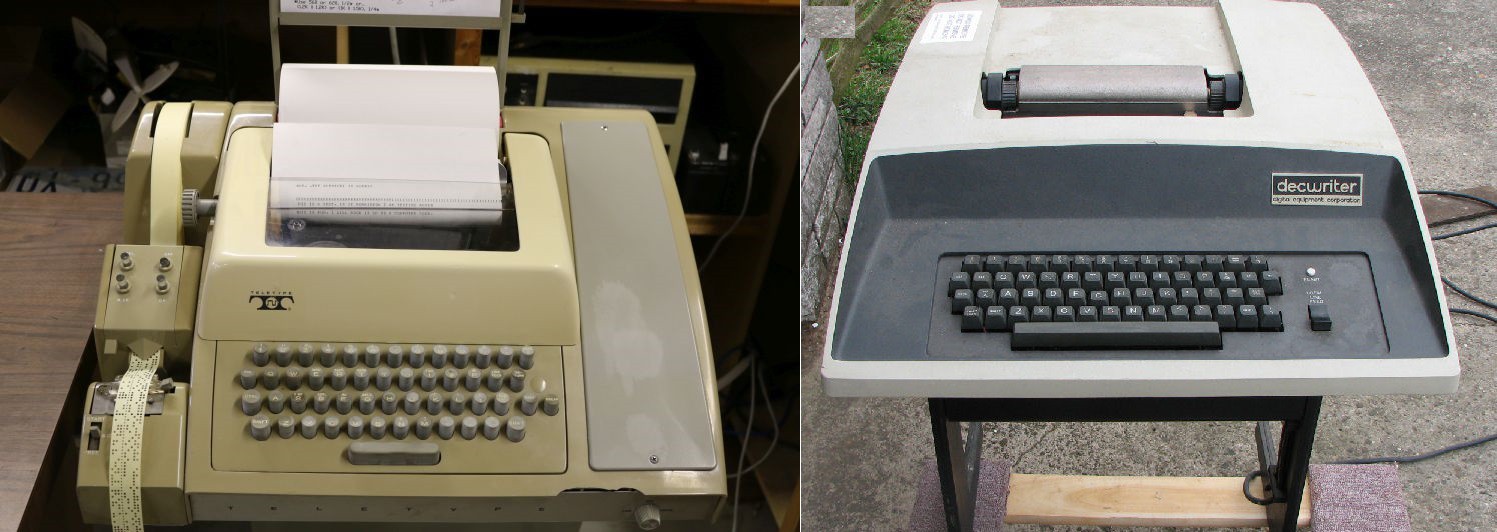
ASR-33 on the left and Decwriter on the right.
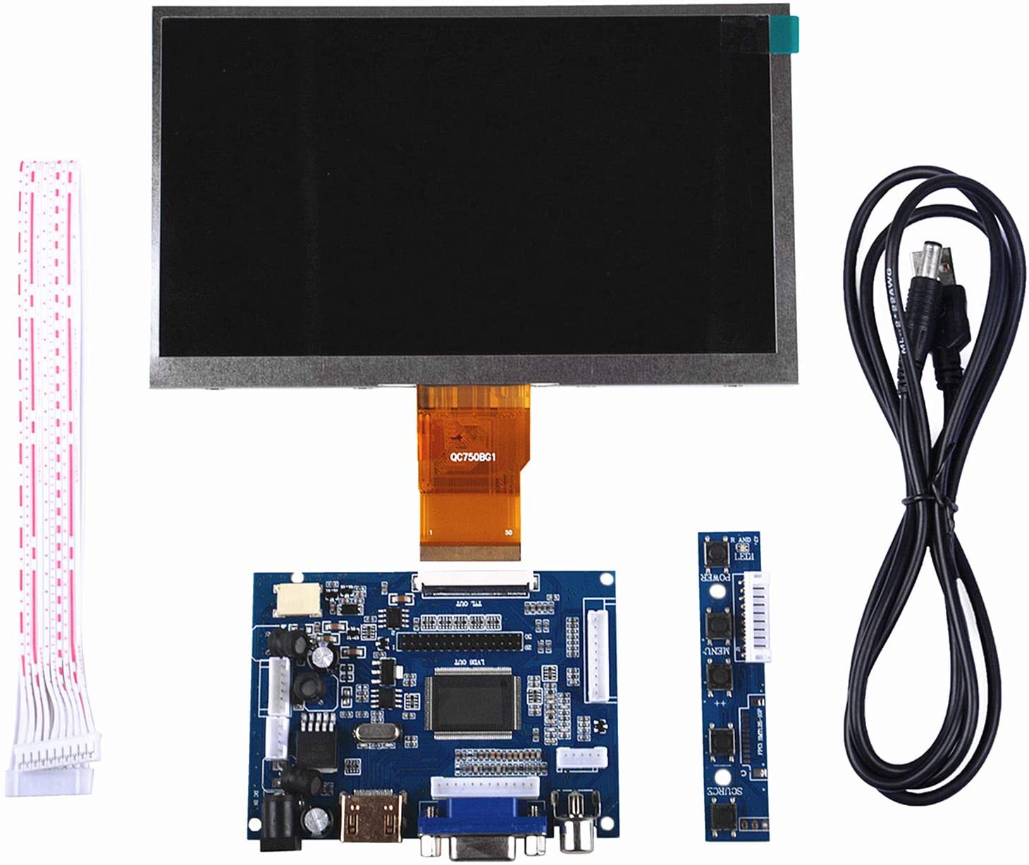
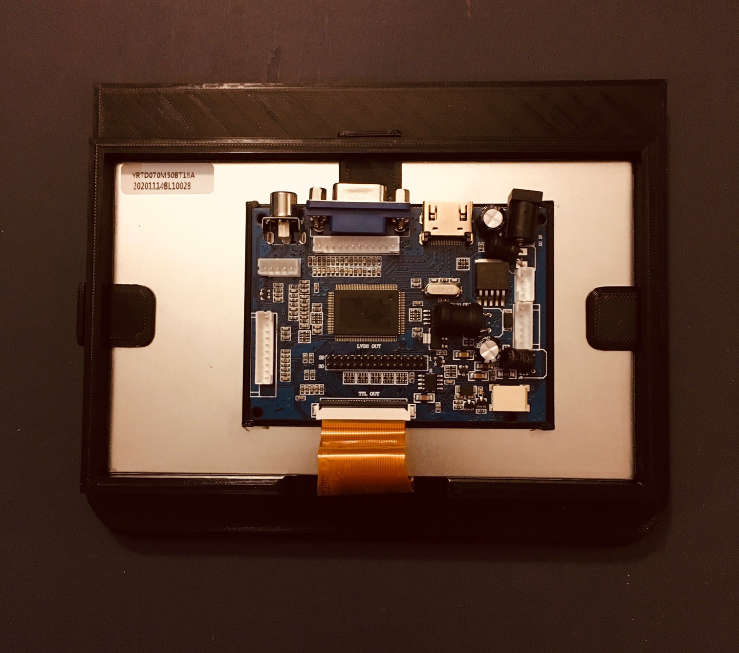
As with the keyboard I determined the optimal size for the scaled down display to be 168 x 126 mm, aligning with the common 4:3 screen ratio of the day. Well you can imagine how hard it is to find a small 4:3 display today. However 7 inch LCD screens a very common, fairly cheap, and their width at around 165 mm is practically perfect for my needs. The 16:9 screen ratio though does shrink the screen height from optimal, but there is not much that can be done about that.
I eventually decided to purchase a GeeekPi 7 inch 1024 x 600 HDMI Screen LCD Display with Driver Board from Amazon.
I prepared the screen for mounting by printing a shallow container to hold the driver board used a Velcro strip to secure the PCB in place. Then I used additional Velcro strips to attach the driver board and caddy to the back of the display.
I had already sliced off the front 25% or so of the terminal model and printed it out as four pieces that I glued together with a CA based gel adhesive (LePage ULTRA-GEL). I couldn't resist adding the Logo that I had printed earlier.
I also designed and printed the front piece to mount the display as well as some tabs to hold it in place.
Mount the display on the back of this piece into the frame provided and secure it in place with the tabs.
Finally insert the display frame and the curved piece at the top into the terminal model and secure it with glue.
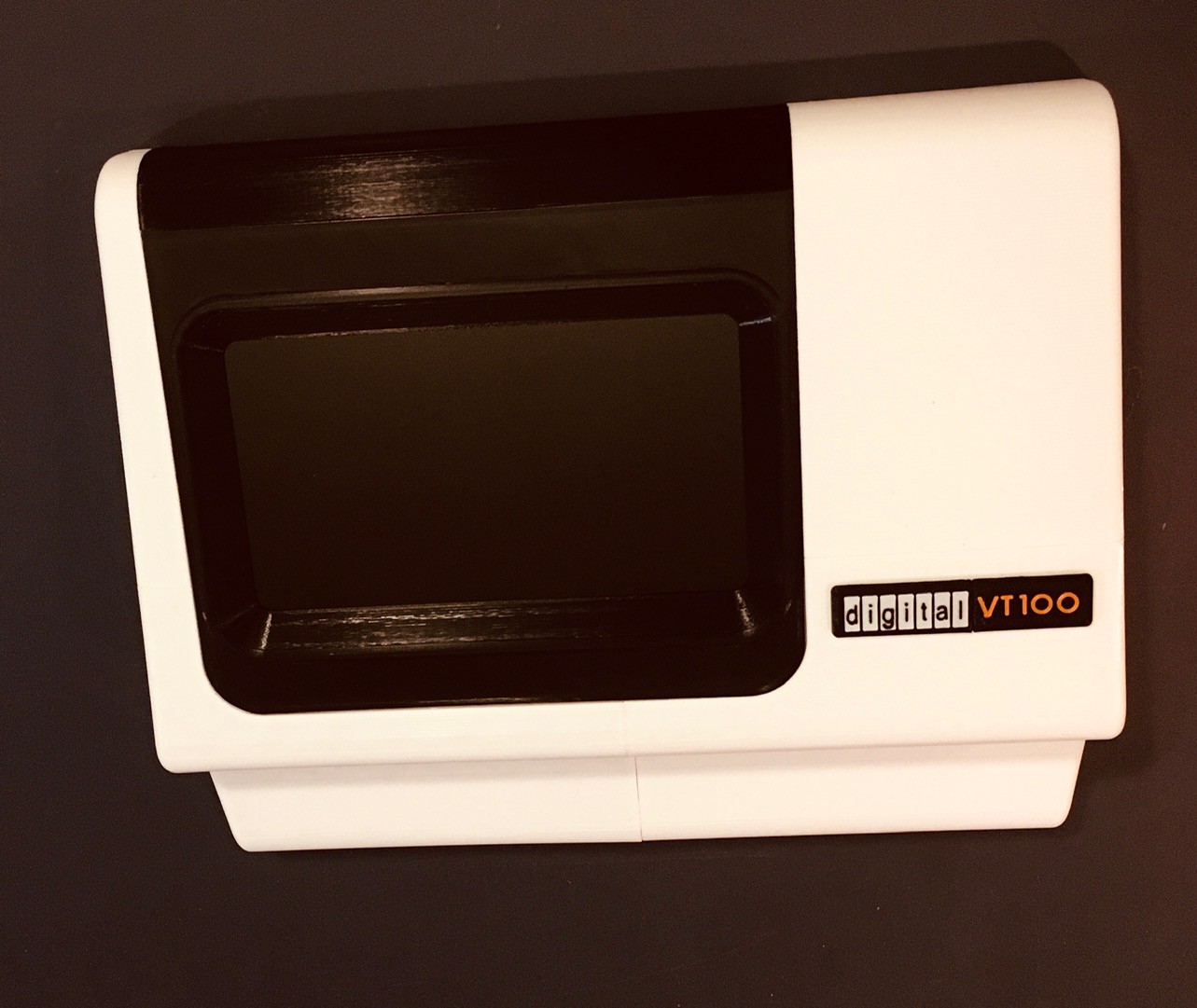
And that's it for now. When I was positioning the actual display in the model, I centered it onto the frame that was holding it. Looking at the integrated unit above with the top curved piece in place it feels a little low to me now. Not sure yet if it's enough for me to spend another nine hours plus filament costs to change it though.
The Façade
It occurred to me at this point that I could almost stop here having achieved most of what I set out to do. With a nice back piece and heavy base holding everything upright, I wouldn't be missing much sitting in front of and using this terminal Façade. I'm going to push on and print the rest but it feels like a viable and even kind of cool option.
I wasn't happy with the way the 7 inch 16:9 display looked.
For one thing it was mounted too low. That could easily be fixed by adjusting and reprinting the black frame. But even then I'm not sure it would look right. So I started searching for an alternative and found a display that I had missed on my first go around that is practically perfect.
This is a PIM372 (Digi-Key part number 1778-1225-ND), an 8 inch 1024x768 XGA display. From the description:
The display's 4:3 aspect ratio makes it a great upgrade for retro gaming builds.
Or retro terminal builds. I had mentioned that the optimal size for a scaled down display to be 168 x 126 mm. Well the viewing area for this display is 165 x 124 mm. It doesn't get much better than that. I reworked the display panel model with the dimensions from the data sheet (outside dimensions 174 x 136 x 3 mm) and found that it will just fit.
So I have one on order. Unfortunately it is delayed in transit at the FedEx Fargo ND facility due to the weather situation down there. I guess I'll just have to be patient.
Update: The display arrived and I was happy to see that it is not in fact monochrome as the Digi-Key description implied.
My 3D printer was going non-stop for ten days or so. When I finally finished printing and installing last piece of the main terminal body I thought I would share.
Unfortunately the join lines are clearly visible. Fortunately I was able to confine the worst of the misalignments to the back of the terminal. Some were due to the print pulling off the bed slightly despite my best efforts to mitigate this. The rest are too bad so I'm NOT tempted to go the bondo and sanding route (I hate sanding).
4:3 Aspect Ratio Makes a Bigger Difference Than I Thought It Would
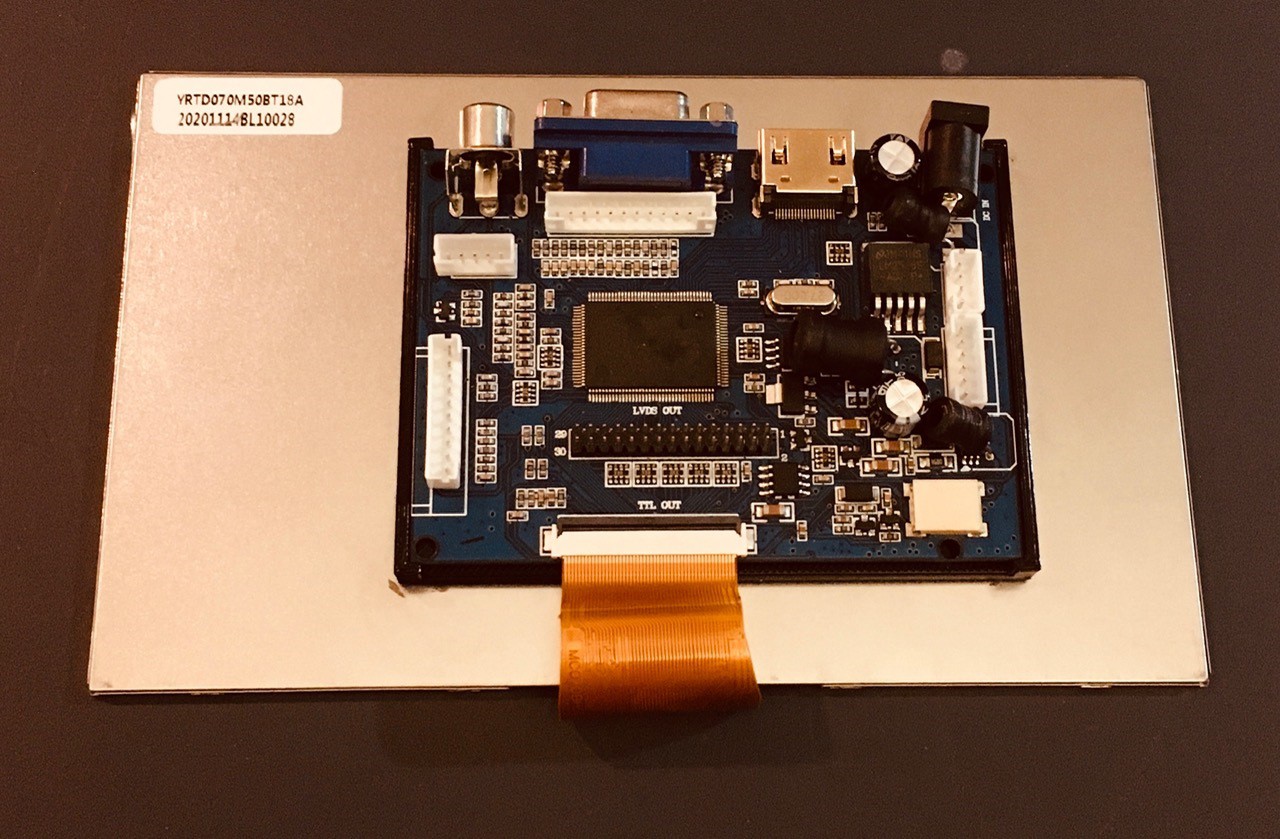
When my new screen finally arrived, I prepared the display the same way as I did the 16:9 aspect ratio panel.
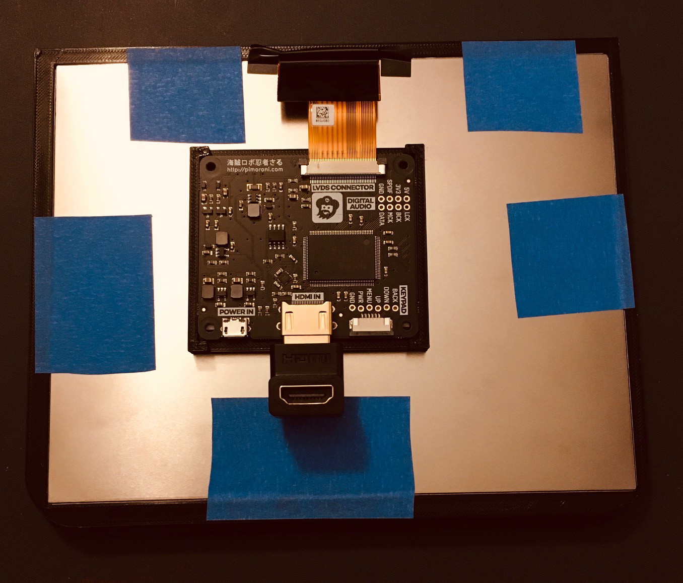
I printed a carrier for the driver board and used two sided tape to hold the PCB in place. Then I attached the carrier and board to the back of the display also with two sided tape. I redesigned the front panel to accommodate the larger screen and mounted the display with painters tape as the was no room to use tabs like I did with the smaller screen. Also note that I added a 90 degree HDMI “elbow “ so that the cable would go straight out the back. Finally I snapped the front and top panels into the terminal frame.
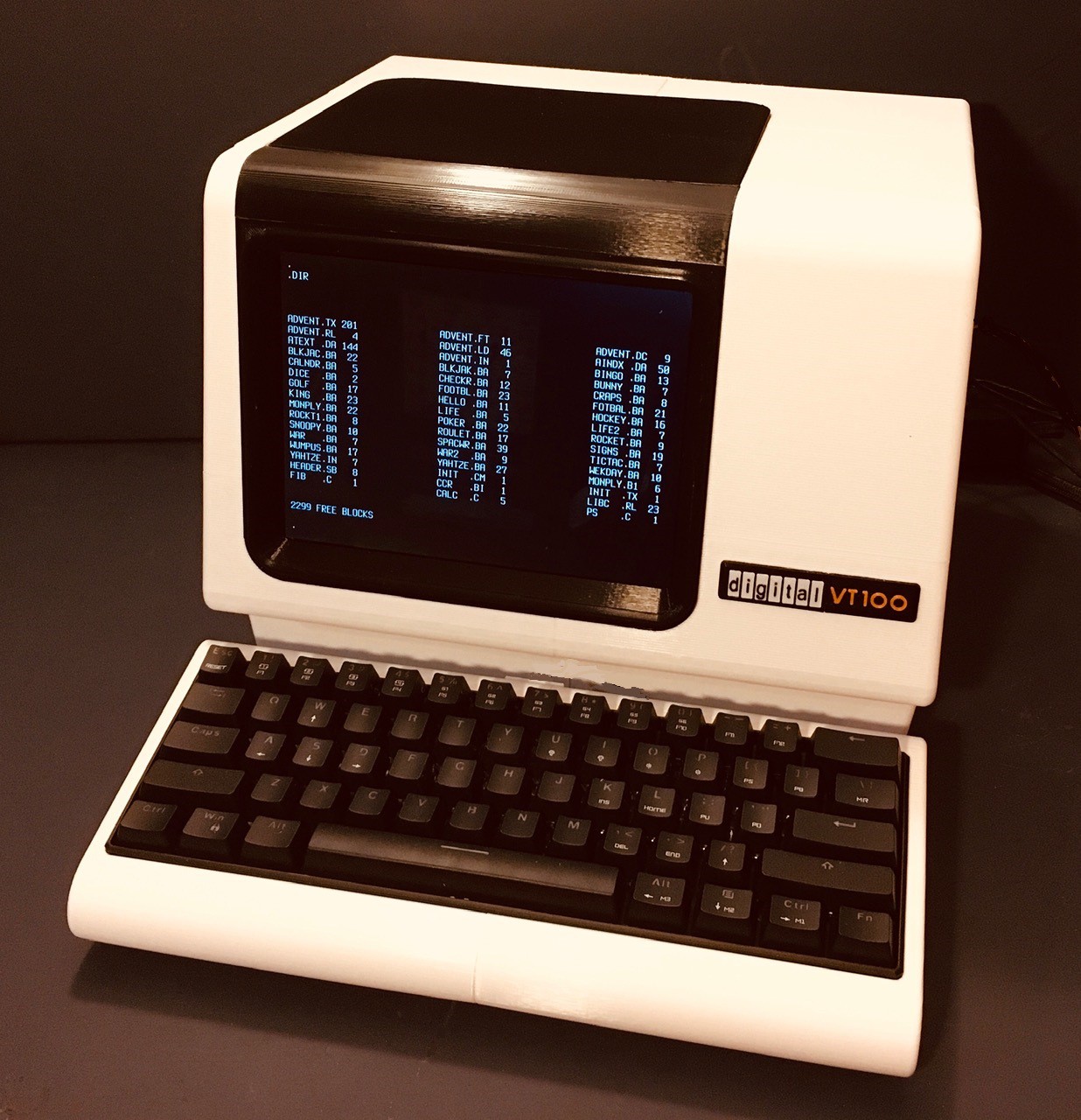
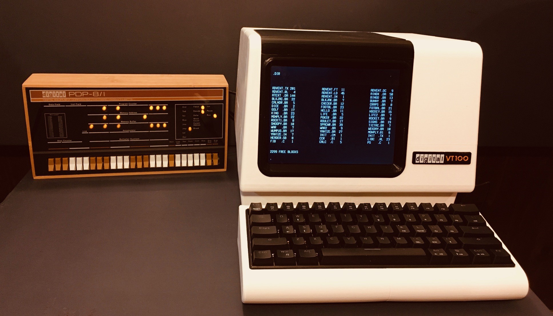
And voila. My finished VT100 2:3 Scale Reproduction. To me this looks so much better than with the smaller screen. I adjusted the font to get as close to an 80 x 24 character layout as I could. Here is a photo of the reproduction and Oscarv's PiDP-8/I.
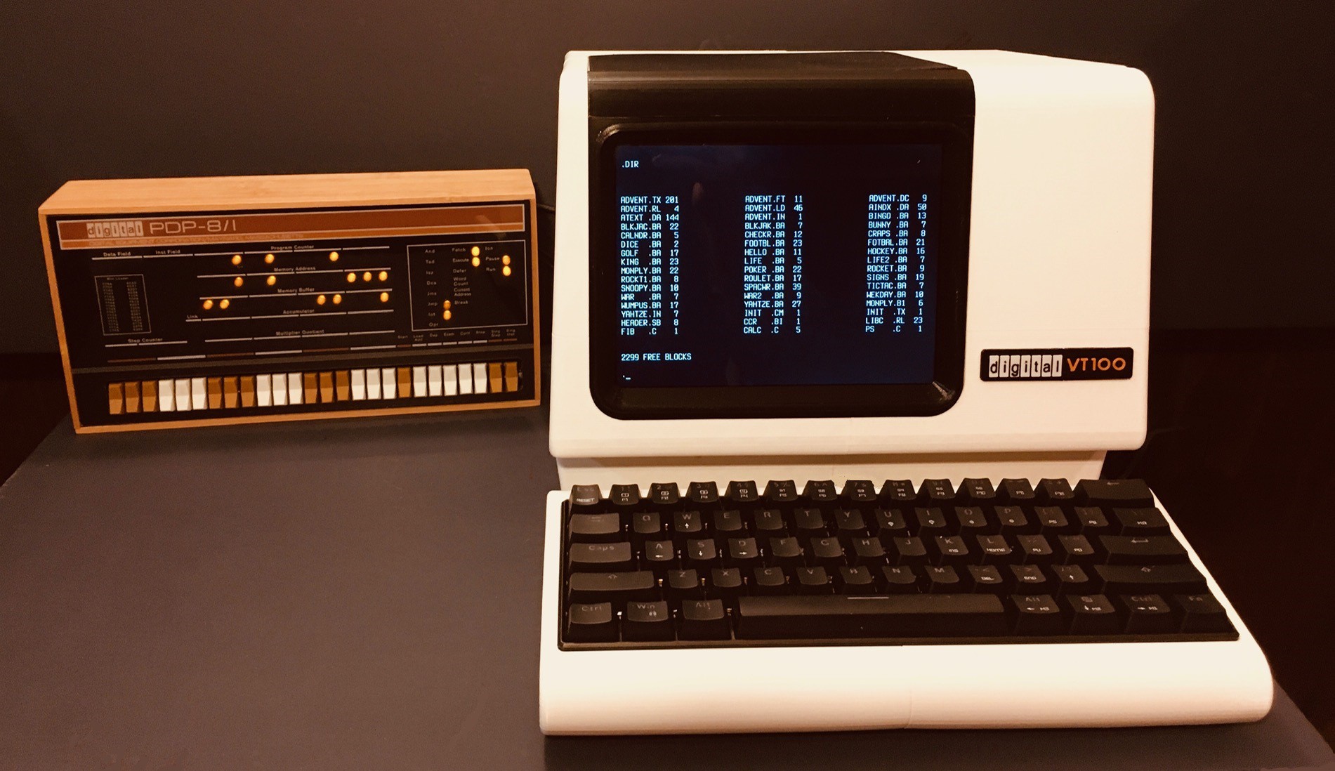
I think they look great together.
When I found the perfect screen for this project, and I saw the following in the product's description:
The display's 4:3 aspect ratio makes it a great upgrade for retro gaming builds.
I knew I was going to try and prove them right. I'll let you be the judge if I succeeded or not.
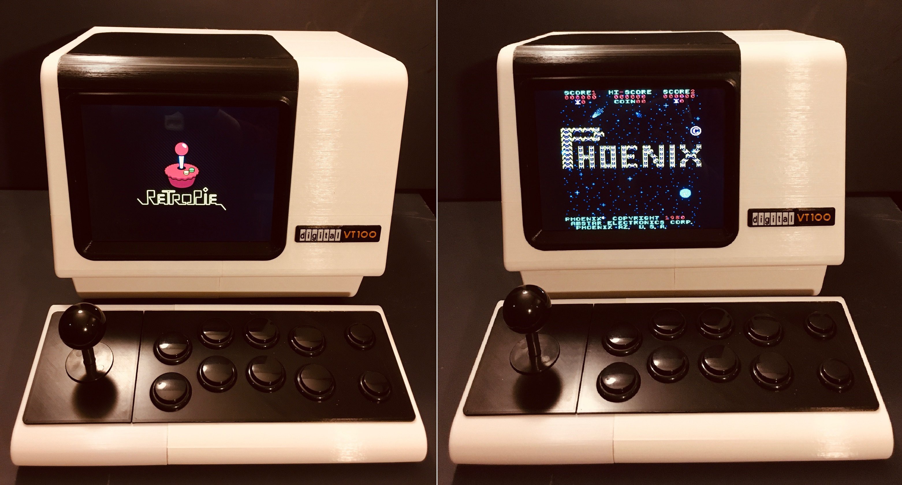
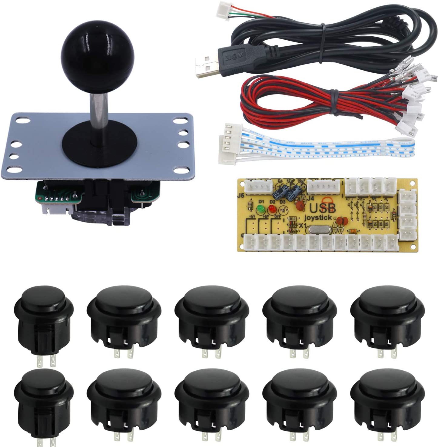
I purchased an arcade controls kit from Amazon.
I modified the VT100 keyboard model and designed a new front face to accept the controls.
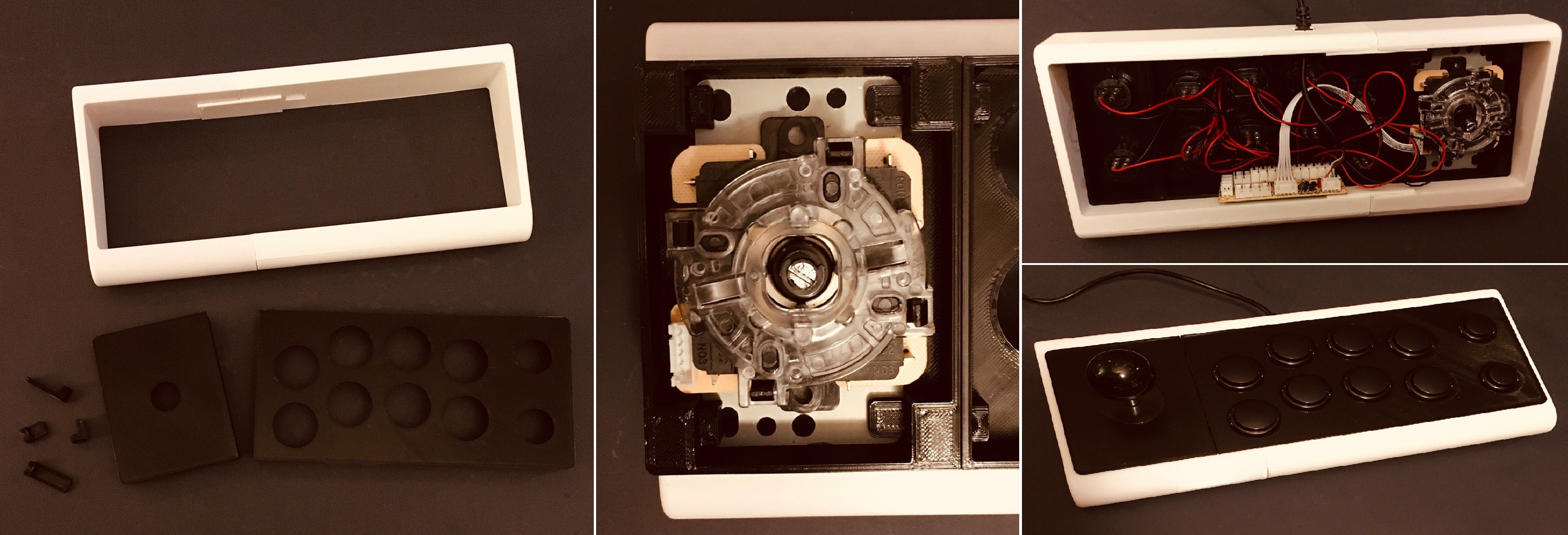
I mounted the joystick in a frame printed on the bottom of the front face and held it in place with some printed "tabs". The longer tabs also join the two front frame pieces together. Wiring is pretty straight forward as the kit comes with a USB interface board and all the cables necessary to build a working arcade console.
I had an Raspberry Pi B laying around which should be OK for the older classic arcade games that I like. I added it to the terminal body and connected it to the display with a short HDMI cable.
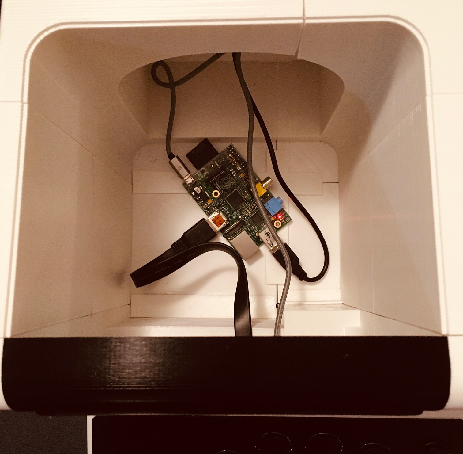
The black cable is the USB connection to the arcade controls, and the two grey cables are power to the Pi and the display. I suppose I could clean this up further with a powered USB hub, but for now it's fine.
I flashed an SD card with the RetroPie image and booted everything up. It all works really well. A scaled VT100 reproduction makes for a pretty funky and unique arcade cabinet.
So I started this journey wanting to build something that I could use as a "front-end" when showing off Oscarv's wonderful PiDP-8/I to my maker mates. The iconic DEC VT100, despite not quite being era authentic, fits the bill nicely. They look great together.
Along the way I was inspired to make a fun variation with my VT100 mini arcade cabinet.

I think of this as my "mullet" project now, business in the front, party in the back. With the addition of an HDMI switch and powered hub you could have both wired up at the same time be able to easily switch between the two modes.
The one thing that I didn't do was create an actual RS-232 terminal. I don't have the bandwidth or a use case for this now, but based on projects like PiTERM, it looks like it would be pretty easy create a third variation that did just this.
This configuration is similar to the Mini Arcade except:
- I plugged in the keyboard to the Pi instead of the arcade controls.
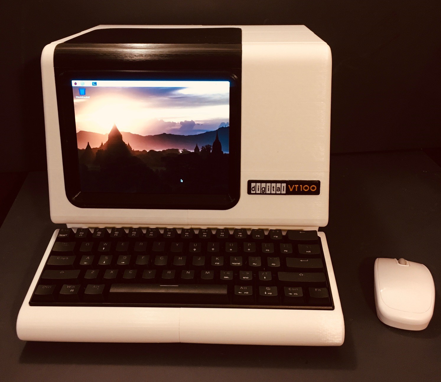
- I installed a Raspbian image on the SD card. I actually have this setup so that I can switch between RetroPie and the Pixel desktop.
- I added a wireless mouse.
Now at this point you could add any software you like. I could see this VT100 Reproduction running all of your home automation for instance. Use your imagination.
Make the VT100 Reproduction Into a True RS232 Terminal
The original incentive for this project was to have a cool looking front end to Oscarv's (https://hackaday.io/obsolescence) wonderful PiDP-8/I (https://hackaday.io/project/4434-pidp-8i) kit. This was accomplished by using the VT100 reproduction as a simple monitor and connecting it to the Raspberry Pi running the PiDP-8/I via HDMI. For fun I then added a Raspberry Pi to the reproduction and created arcade and desktop versions. What I didn't do is configure the VT100 as a terminal, which of course is it's original purpose. Well I'm going to fix that now.
The key to making this work is an RS-232 hat for the Pi.

I purchase this and when it arrived realized that the Raspberry Pi I had been using was an older model with the 28 pin GPIO connector. So I ordered a Raspberry Pi 4 which has the added benefit of being able to run a much wider range of RetroPie games, and is a more capable desktop machine.
So when I put it all together the hardware looks like this:
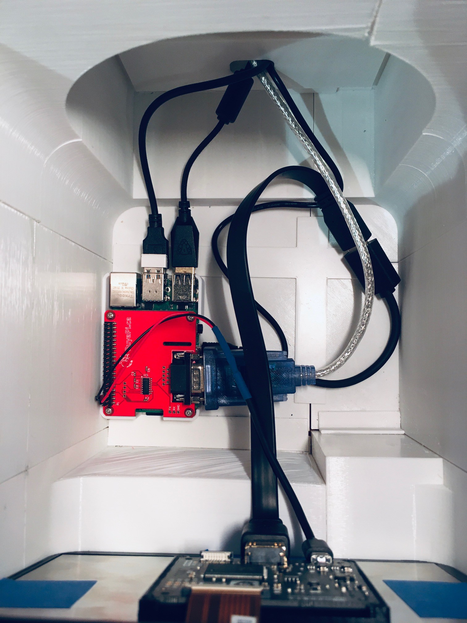
So here's what's going on:
- It's a little hard to see but I printed a "caddy" for the Pi (with hat) and glued it to the bottom of reproduction. I then secured the Pi into this holder with double sided tape.
- I chopped a short micro USB cable and added wires with female headers for the power and ground line. I plugged the micro USB connecter into the display's power jack and attached the wires to +5V and GND on the Raspberry Pi GPIO pins.
- Similarly the HDMI from the display is connected to one of the micro HDMI connectors on the Pi.
- The rightmost black cable coming in is the USB C power cable attached to the Pi.
- The silver cable with the blue plug is the RS-232 cable. More on this in a bit.
- The white USB dongle is for the wireless mouse. Of course a wired mouse would be OK too.
- And finally the remaining two USB cables are for the keyboard and arcade controls.
So not only does this add RS-232 capability to the build but consolidates and improves the other features as well.
Software
As I did what I described in previous sections, I first setup my new Pi 4 with the latest RetroPie image. There is great documentation on how to do this at RetroPie Docs.
To install the Pixel desktop, go to the RetroPie configuration page and select 'RetroPie Setup'. Then select 'Configuration/Tools' from the setup menu. From the displayed options menu select 'Raspbian related tools', then select 'Install Pixel Desktop environment'. Once done you should be able to switch to the desktop by selecting Ports/DESKTOP from the RetroPie menus.
Before we can get the RS-232 working we have to tweak the Raspbian image a bit. Switch to the Pixel desktop and open a terminal window. If you'd like to communicate with a serial device then we need to edit the boot cmdline.txt file. Before we edit this file its a good idea to take a backup of it:
sudo cp /boot/cmdline.txt /boot/cmdline.txt.backup
Now we can edit the original:
sudo nano /boot/cmdline.txt
You then need to remove the following text:
console=serial0,115200
Save the changed file. Before this change will take effect you will have to reboot the system.
Now that we have stopped the Pi from using the serial to output its console data, we can use the serial port with our own software. I tested the serial port with minicom. From a command window install minicom.
sudo apt-get install minicom
Then to run minicom enter the command:
minicom -b 9600 -D /dev/serial0
You can of course change the baud rate to whatever is appropriate.
Testing
So how can you make sure that the RS-232 serial port is working correctly? Well you have to attach it to something. Now I don't have another device with an RS-232 port, and none of my computers have one. But I do have a lot of available USB ports so the simplest thing to do is invest in a USB to RS-232 adapter cable. Here is the one that I purchased on Amazon (DTECH 6 Feet USB 2.0 to RS232 DB9 Female Serial Adapter Cable).
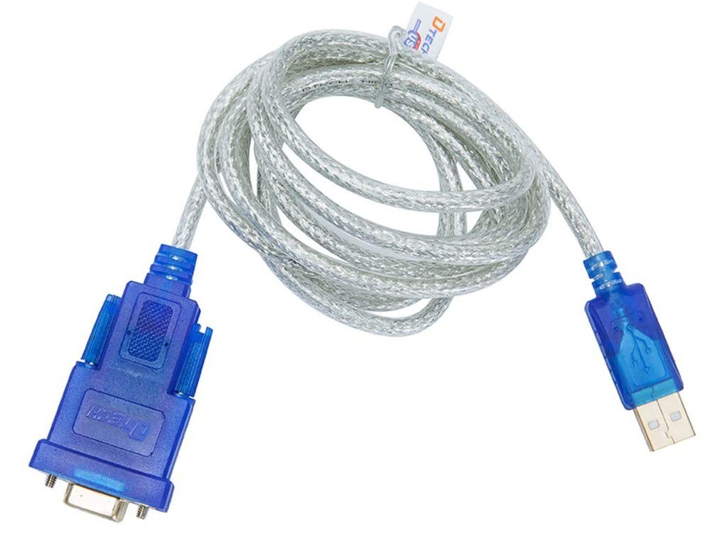
I attached the DB9 connector to my RS-232 hat and the other end to a free USB port on my laptop. Make a note of the COM port that the cable attaches to. Then I needed to run a terminal program on my laptop. Fortunately I have Putty which supports serial.
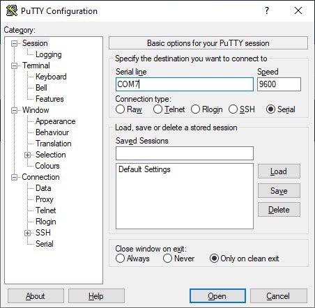
Here I selected the Serial radio button and entered the COM7 port the cable was using and the baud rate to use. When I clicked open I was able to type into the terminal window and see the characters appear on the VT100, and likewise type into minicom and see the characters appear in Putty. Serial working!
Connecting to the PiDP-8/I
I'm kind of coming full circle here. I now want to establish a serial connection to the PiDP-8/I. My first thought was to get another RS-232 hat for the Pi running the PiDP-8/I. Unfortunately the PiDP-8/I software uses practically all of GPIO pins including the ones used for serial connection. Oscar's suggestion in the PiDP-8/I documentation is for: "a real VT-100, VT-220 or similar serial terminal. Use a USB-RS-232 adapter cable. They cost $5 or so (search on Aliexpress and similar sites)." Just like the one I purchased. How fortunate ;-)
Before you can use the cable as Oscar puts it " Some Linux-foo is required to set up the [PiDP-8/I] Pi so that it has a console port assigned to the USB-Serial port.". Here is what to do (reproduced from this link for your convenience).
1. Copy the file 'serial-getty@.service' from '/lib/systemd/system' to
- '/etc/systemd/system' (for standard Raspbian)
- '/etc/systemd/system/xyz' - where xyz is a 'wants' subdirectory whose exact name I forgot, but it'll be obvious.
This file is a generic template for setting up a serial terminal with a log-in prompt. 2. The file must be renamed, so that it points to your serial terminal which will be ttyUSB0. The filename becomes:
'serial-getty@ttyUSB0.service'
3. The file may need to be edited with the parameters of your serial terminal, or the default setting may work. In my case I changed the first line in the [Service] section to read:
ExecStart=-/sbin/agetty ttyUSB0 9600 vt100
4. Now, enable the service with:
'sudo systemctl enable serial-getty@ttyUSB0.service'
You should get a 'Creating sim link ....' message. The service will now start up at every boot.
Once done, connect the cable to the USB port on the PiDP-8/I and the RS-232 DB9 port on the VT100. From the minicom terminal on the VT100 you should now be able to press Enter and see a login prompt for the PiDP-8/I.
One other thing I did on the VT100's Raspberry Pi was to change the font for terminal window to be something more appropriate for the era (and save eyestrain). This involves editing a system file called “console-setup”. You just need to load it into your preferred text editor and tweak a few lines :
sudo nano /etc/default/console-setup
Change the FONTFACE and FONTSIZE lines to :
FONTFACE="Terminus"
FONTSIZE="14x28"
Save this file and reboot. This will set the terminal window on the VT100 to be 72 characters x 25 lines which looks really good IMHO.
Running the Applications
When you power up the VT100 reproduction it will boot into RetroPie for your arcade pleasure.
If you want to use the Pixel desktop you can use the RetroPie menus to select Ports then DESKTOP. To get back to RetroPie select the Shutdown... menu item then select Exit to command line.
To connect to the PiDP-8/I bring up the RetroPie Main Menu and select QUIT then select QUIT EMULATIONSTATION. This will bring you to a full screen command prompt. From here fire up minicom:
minicom -b 9600 -D /dev/serial0
then login to the PiDP-8/I and follow the Obsolescence Guaranteed instructions to get to the OS/8 prompt. If you exit minicom you will be able to get back to RetroPie by running the emulationstation command.
Wrapping Up Again
I feel better now with my VT100 reproduction fully supporting RS-232. The terminal, arcade, and desktop functions are now much more integrated. It's just a tidier more polished project now. Well worth the effort.
Better VT100 Emulation
Background
Most terminal emulators like xterm and PuTTY take raw text and formatting instructions and interpret them to display formatted text on the screen like the original hardware did. However they are software only constructs that are derived from the documentation supplied with say an actual VT100 terminal, hence the "emulator" moniker. So in the previous section I used one of these documentation based emulators, minicom, to test my RS-232 connection. It works pretty well and is probably a reasonably accurate reproduction of the original VT100 terminal behavior.
But what if we could do better. Thanks to Lars Brinkhoff we are able to do just that. His terminal-simulator project can be found over on GitHub. What makes this better? The About from his readme:
This is a software simulation of the VT100 hardware. The original firmware ROM is built in and executed by an 8080 emulator. Other components include video display with character generator ROM, settings NVRAM, Intel 8251 USART, and a keyboard matrix scanner.
This is a relatively new project, still under active development, but I can tell you from personal experience it works quite well. While this is still a software construct, by running the code from the actual VT100 ROMs you are going to achieve much more accurate experience.
Running the Simulator
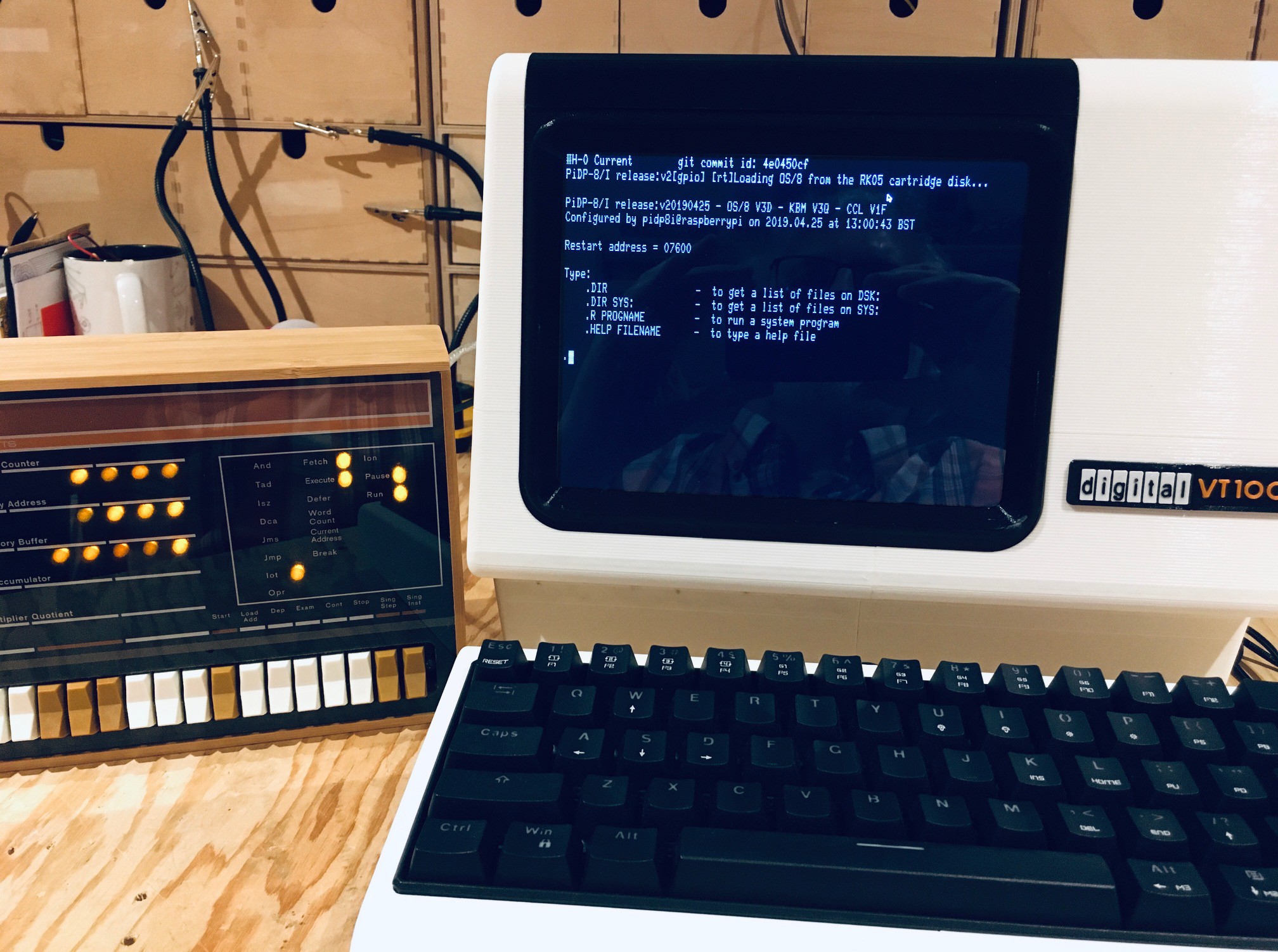
I downloaded the code from the terminal-simulator repository and unpacked it onto the Pi in my VT100 reproduction. I ran a make from within the vt100 folder. I was then able to run the following command from the same vt100 folder:
./vt100 /dev/serial0
This resulted in a blank screen with a blinking box cursor in the upper left corner. I immediately pressed F9 which put me in the SET-UP screen.
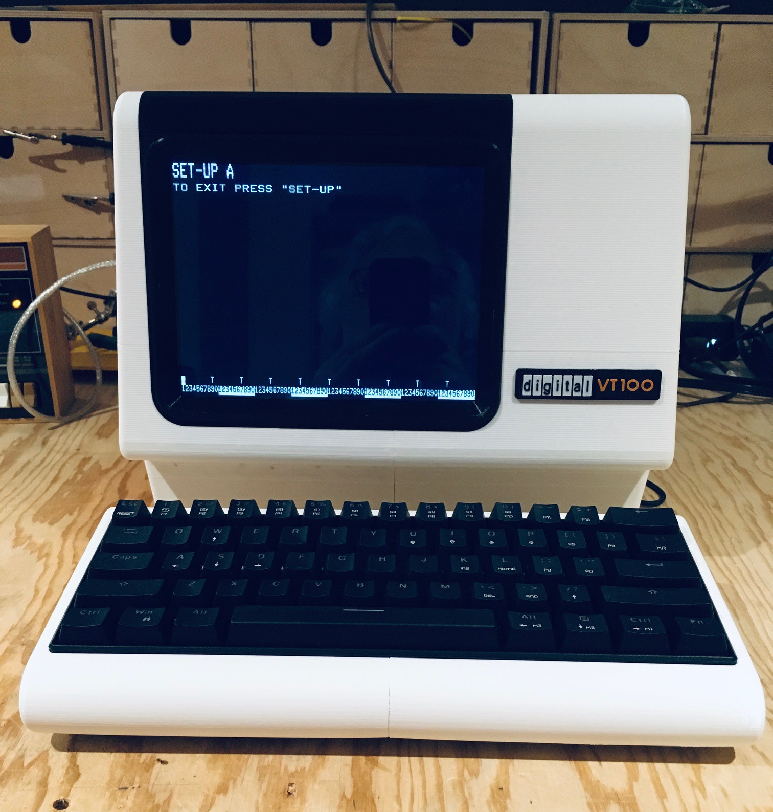
Wow. When you see the SET-UP screen pop up you really know that this is the real deal. The one change you want to make here is to set the SCROLL option to JUMP. SMOOTH scrolling isn't quite ready yet.
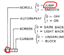
From the VT100 User Guide you would do this by:
- Press 5 to switch to the SET-UP B screen.
- Move the cursor to be on top of the first number in the first block of 4 options.
- Press 6 to change the value from 1 (SMOOTH) to 0 (JUMP).
- Press F9 to exit SET-UP.
Now at this point you should be able to press Enter to get the login prompt for the PiDP-8/I machine. Log in and run the emulator just as you did with minicom.
You can exit the simulator by pressing Ctrl-F11.
When I saw these screens I commented to Lars:
I am loving the look of the screen! With our modern smooth looking anti-aliased typefaces we forget the blocky pixelated letters of terminals past. I really want this look for my VT100.
This makes the whole VT100 experience so much more authentic. Thank you Lars for making this happen.
Even Though He's Using Shaders, It's Getting Warm In Here
Lars Brinkhoff continues to improve his VT100 simulator software. From one of his project logs:
I'm adding the use of OpenGL shaders to mimic a CRT. This includes effects such as characters built from smooth scanlines, a soft glow around text, and a subtle curvature as a CRT should have.
This stuff looks great! When I began using some of this new code I started seeing the dreaded Raspberry Pi OS temperature icon popping up.

Using the GPU based shaders does increase the thermal load on the Pi, but this is no reflection on the code that Lars is writing. It does however show what a poor job that I did managing heat dissipation. I should have known better given the Raspberry Pi 4's reputation for running hot.
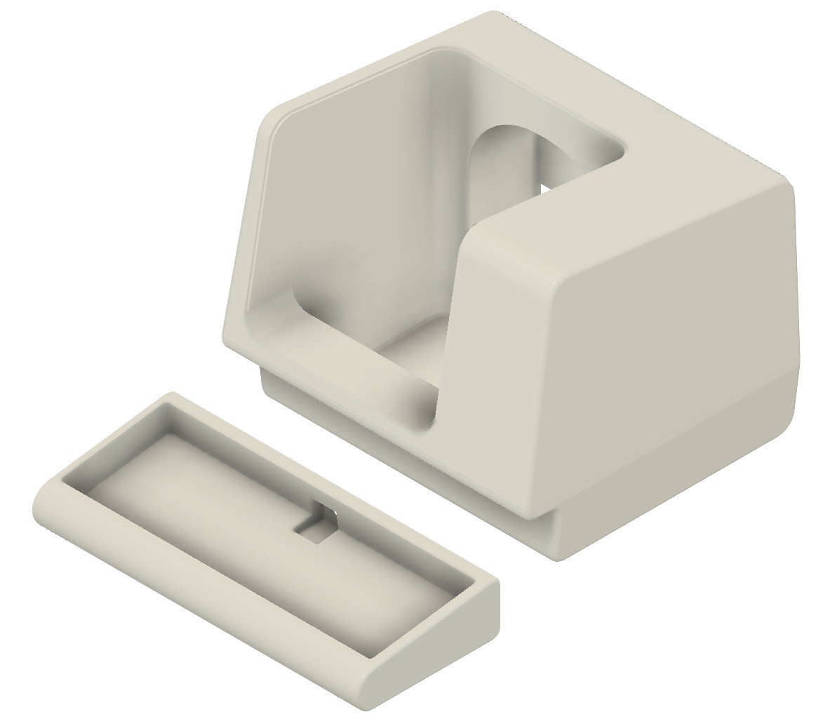
So I did a few things to mitigate this issue. First of all I added heat sinks to the major components.
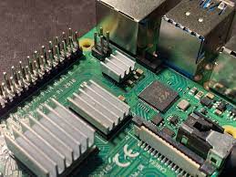
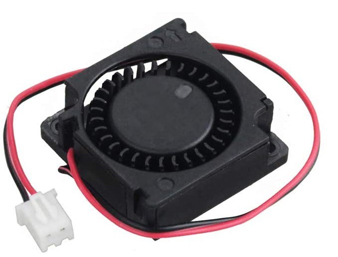
More importantly I redesigned the "caddy" I use to hold the Pi 4 in place to be more open and added a small 30 mm x 30 mm x 10 mm blower fan for good measure.

The original in the upper left was trapping the heat in especially with the RS-232 hat attached. The fan on the new design is attached directly to +5V and GND GPIO pins on the Pi. It runs pretty quietly especially when the top panel is in place on the terminal body.
I have not seen the thermometer pop up since I have made these changes.
I have added the STL file for the Pi holder to GitHub. The fan I used is from Amazon: GDSTIME 3cm 30mm x 10mm 5V DC Brushless Small Blower Cooling Fan, with Dual Ball Bearings