 Subhajit
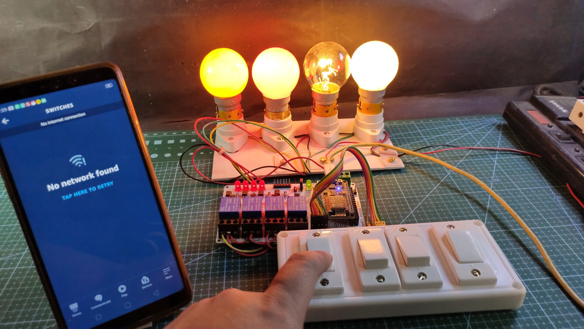
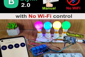
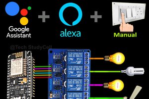
This NodeMCU Alexa control smart relay has the following features:
1. Control home appliances with voice commands using Alexa
2. Control home appliances with manual switches.
3. Monitor real-time feedback in the Alexa App.
4. Control home appliances manually without internet.
If the internet is not available, then you can control the home appliances from manual switches. During the article, I have shown all the steps to make this smart home system.
Required Components for the PCB
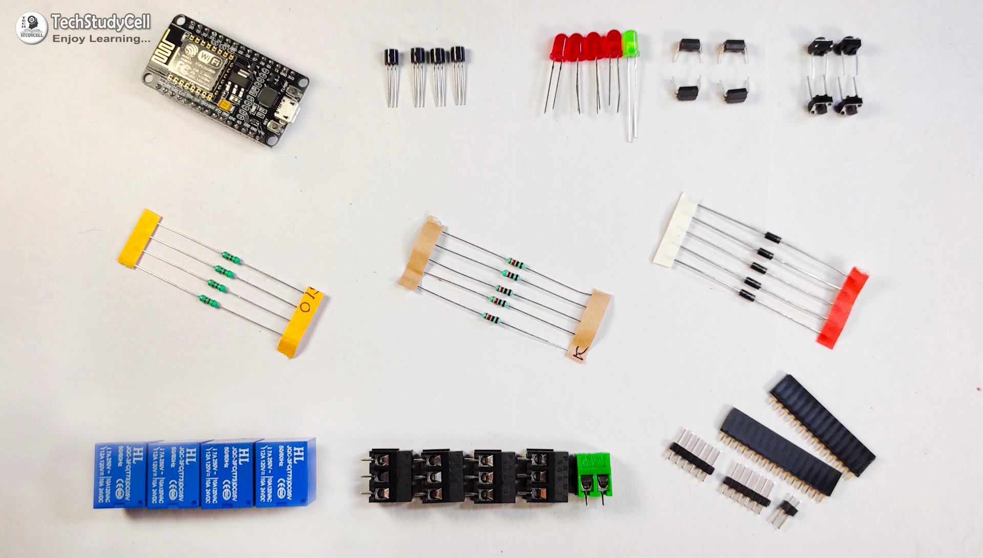
1. Relays 5v (SPDT) (4 no)
2. BC547 Transistors (4 no)
3. PC817 Optocuplors (4 no)
4. 510-ohm 0.25-watt Resistor (4 no) (R1 - R4)
5. 1k 0.25-watt Resistors (5 no) (R5 - R9)
6. LED 5-mm (5 no)
7. 1N4007 Diodes (4 no) (D1 - D4)
8. Push Buttons (4 no)
9. Terminal Connectors
10. 5V DC supply
11. NodeMCU board
Required Software:
1. Arduino IDE
2. Amazon Alexa App
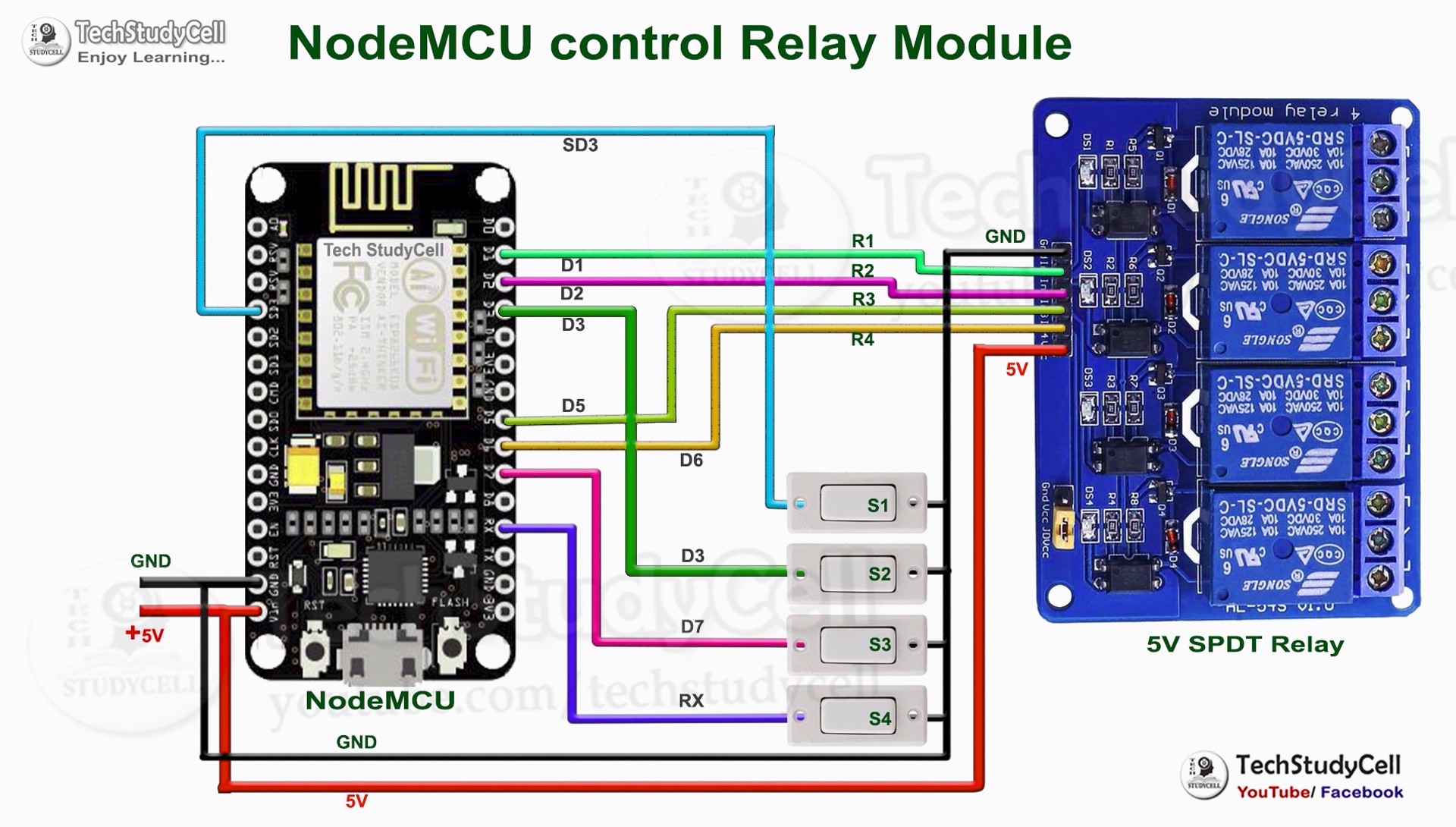
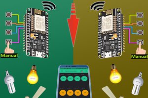
This is the complete circuit diagram for this home automation project. I have explained the circuit in the tutorial video.
The circuit is very simple, I have used the GPIO pins D1, D2, D5 & D6 to control the 4 relays.
And the GPIO pins SD3, D3, D7 & RX connected with switches to control the 4 relays manually.
I have used the INPUT_PULLUP function in Arduino IDE instead of using the pull-up resistors.
I have used a 5V mobile charger to supply the smart relay module.
Control Relays With Voice Commands Using Alexa
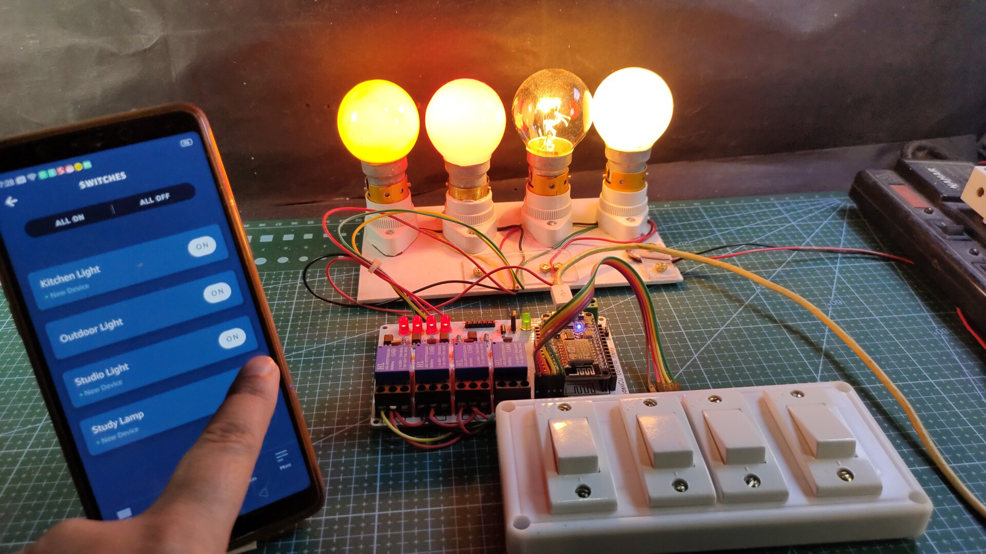
If the NodeMCU is connected with the WiFi, then you can control the home appliances from Amazon Alexa App and also from the manual switches.
You can control, monitor the real-time status of the relays in the Alexa App from anywhere in the world.
You don't need an Alexa device for this home automation project.
Control Relays Using Switches:
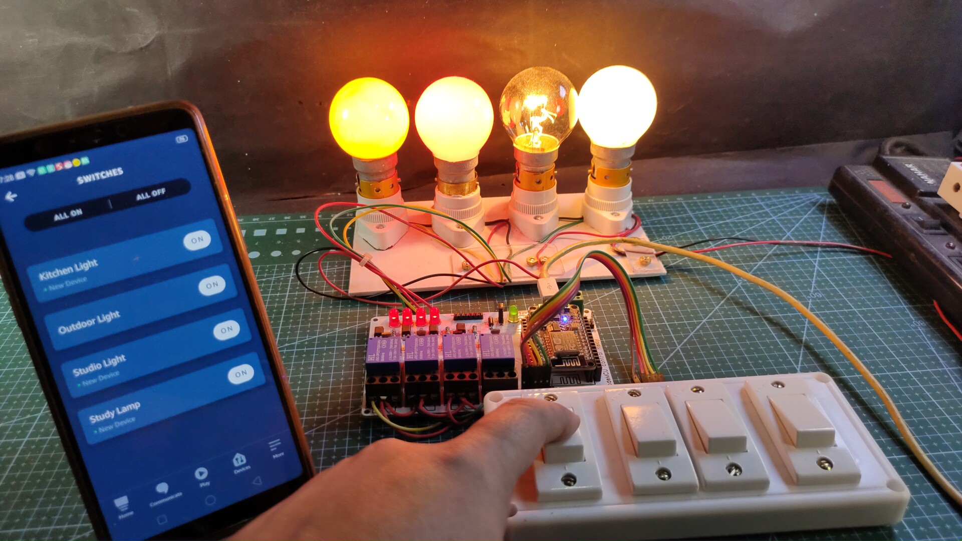
If the WiFi is not available, you can control the relays from the manual switches.
The NodeMCU will check for the WiFi after every 5 seconds. When the WiFi is available, the NodeMCU will automatically connect with the WiFi.
Please refer to the circuit diagram to connect the manual switches.
Create an Account in Sinric
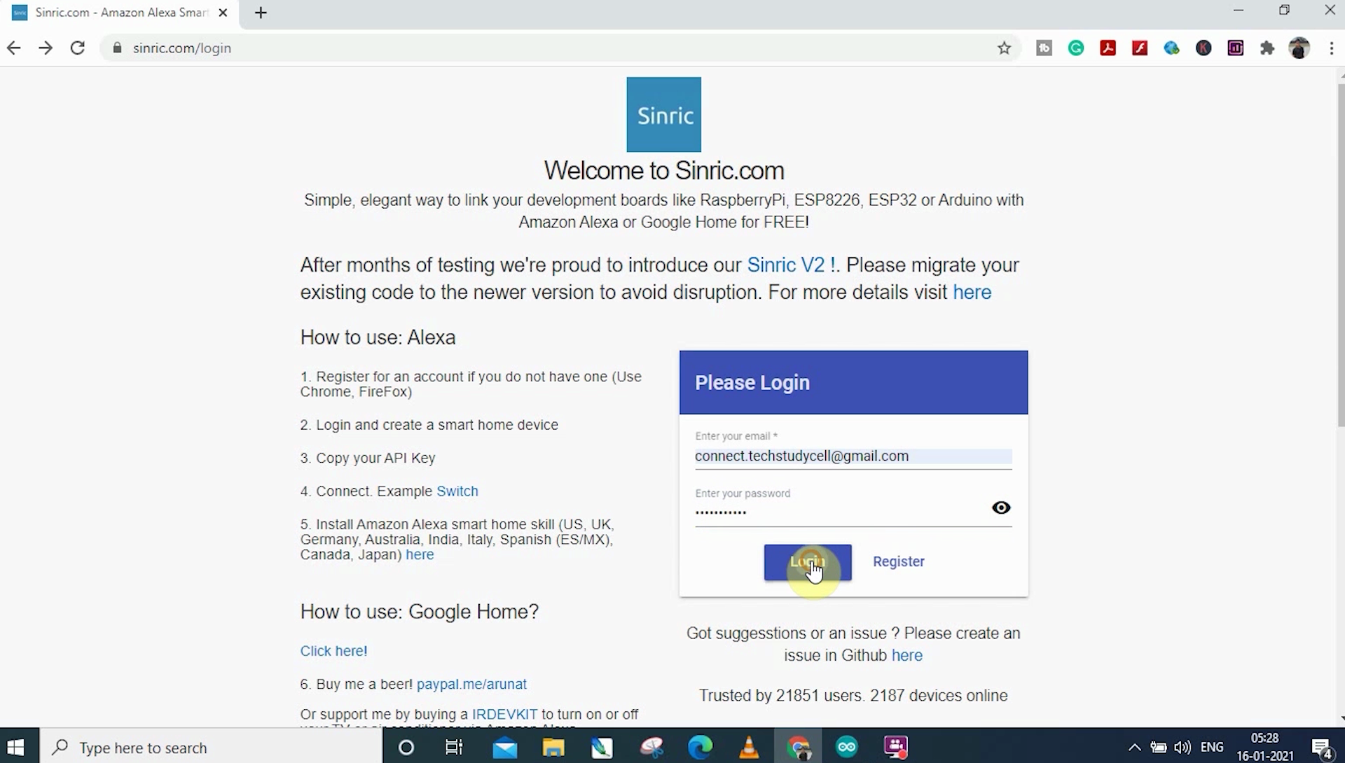
First, visit https://sinric.com/login
Click on Register.
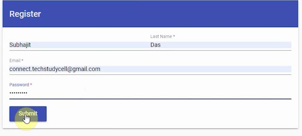
You have to create an account in Snric.
Then log in to Sinric Account.
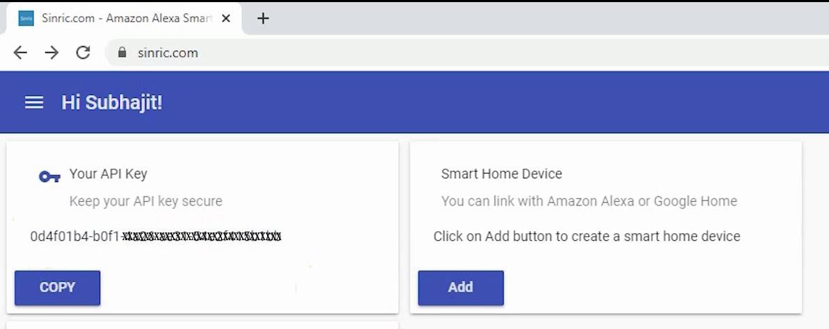
You will get an API key which will be required in the code.
Now click on Add.
Add Devices in Sinric
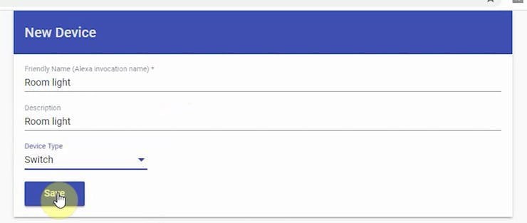
Then enter a name for the device. Alexa will identify the device with that name.
Select the type as Switch.
Click on Save.
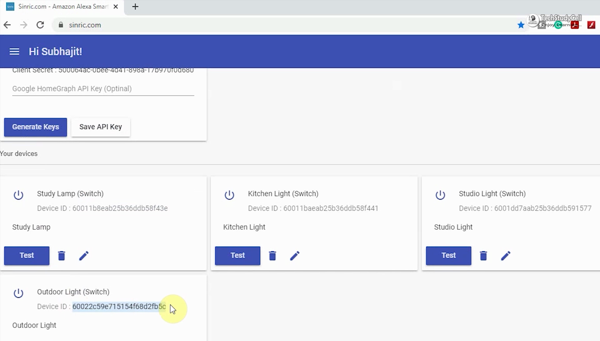
In this way add 4 devices in Sinric. Each device will get a unique device ID.
Program NodeMCU Using Arduino IDE
First, you have to install the required libraries. I have shared all the links in the code.
Then enter the API key & WiFi credentials
#define MyApiKey "----------------"
#define MySSID "--------"
#define MyWifiPassword "------"
Then enter the device IDs for each device
String device_ID_1 = "------------------------";
String device_ID_2 = "------------------------";
String device_ID_3 = "------------------------";
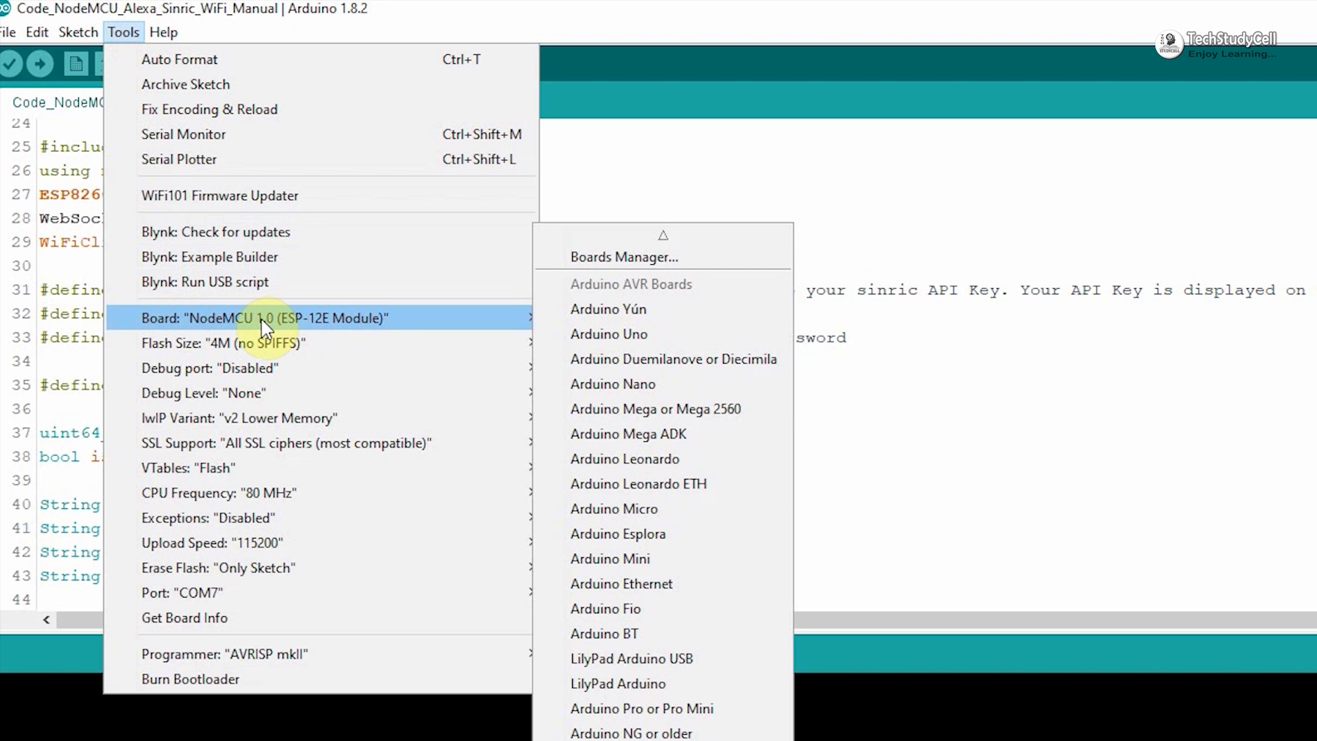
String device_ID_4 = "------------------------";After that select the NodeMCU 1.0 (ESP-12E module) board and the PORT. Then click on the upload button.
Download and Install the Amazon Alexa App

Configure the Alexa App for This Smart Home System
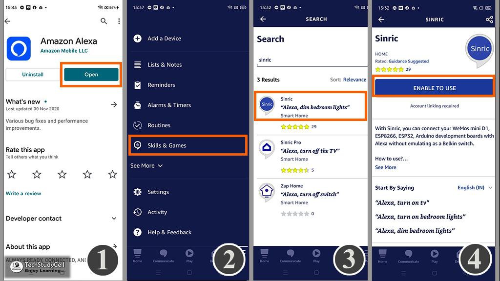
Go to "More", then select "Skills & Games" Search for Sinric and tap on "Sinric". Tap on "ENABLE TO USE"
Connecting Devices With Alexa
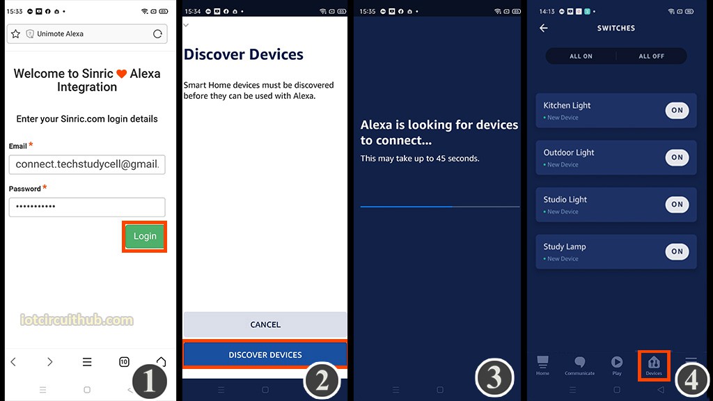
Log in with the Sinric account credentials.
Goto Alexa and tap on "DISCOVER DEVICES".
It will take a minute to add devices. During this time the NodeMCU should be connected with the WiFi.
Tap on "Devices", and tap on "Switch" to see all the devices.
Design the PCB for This Smart Home System
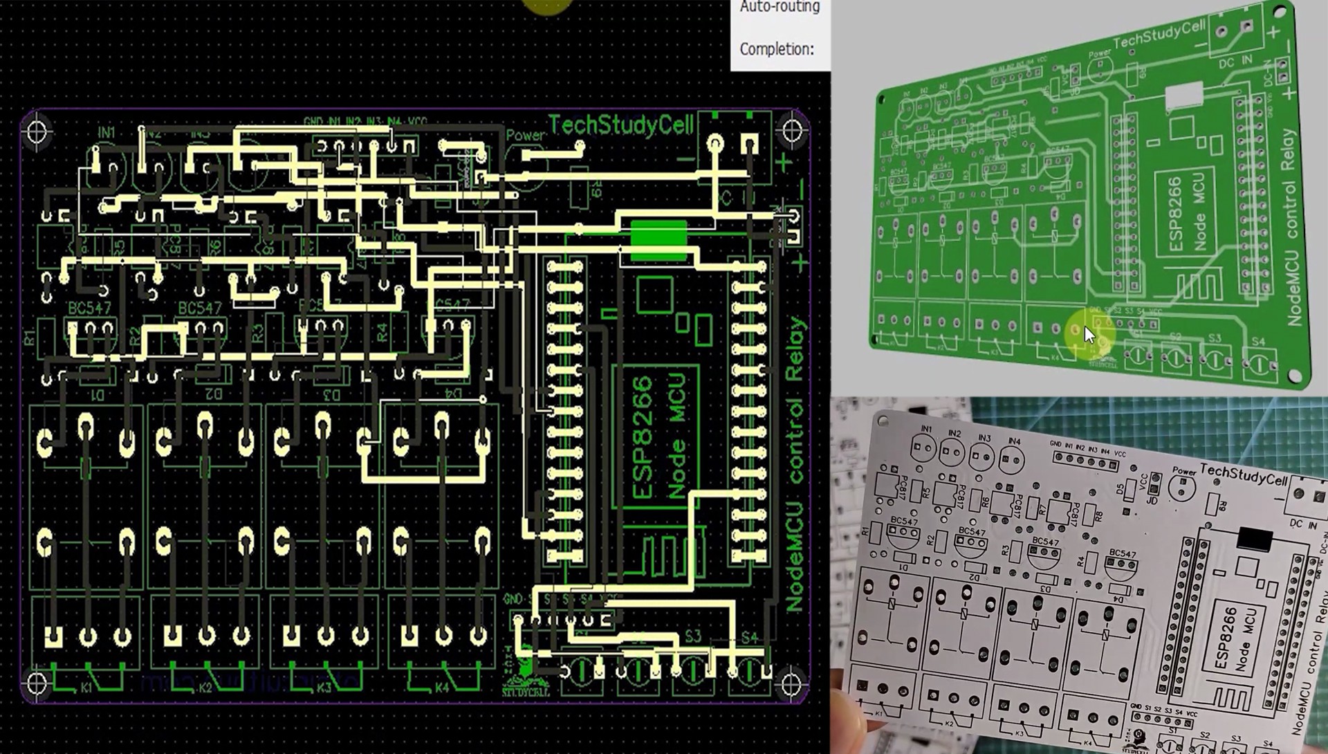
To make the circuit compact and give a professional look, I have designed the PCB after testing all the features of the smart relay module.
You can download the PCB Gerber file...
Read more »

well done and well documented