Close
0%
0%

PS - I Hate You

A love letter to all our fellow circuit board artists who hate it when components aren't perfectly aligned at 45 and 90 degrees.

Similar projects worth following
298 views
0 followers
A surface mount solder-it-yourself kit where nothing is at a normal angle. Use it as positive affirmation or give it to a friend passive-aggressively! Whatever you choose, it's sure to warm the cockles of your heart. The circuit uses two 555 timers to produce a heartbeat-like blinking pattern, there's an ON/OFF switch, and a blinking/solidly lit switch, and it uses 0805 and bigger components. See? I was actually being really nice. I could have made it all 0402s.

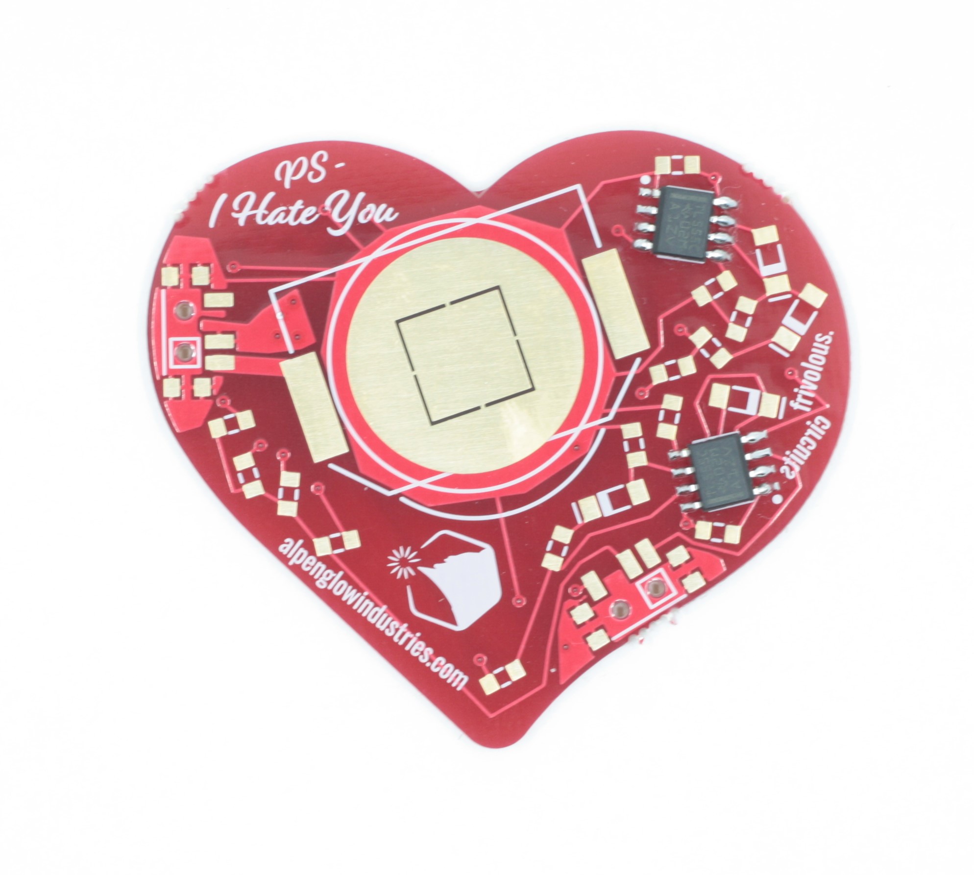
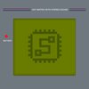
I came up with this project after reading this snarky tweet about how the RPi Pico was "literally unusable" because a trace was at an odd angle.  Having been designing circuit boards for 20+ years, I thought the resulting thread was hilarious.  There were also pictures of other really weird cringe-worthy layouts, and I thought "Heh, it would be fun to do a terrible layout on purpose, as if you just threw a handful of components on a board and they stuck wherever they landed."  Then I thought "Hey, Valentine's Day is coming up, I could make it a snarky Valentine because that holiday is total BS anyway."  And thus, PS - I Hate You was born!  

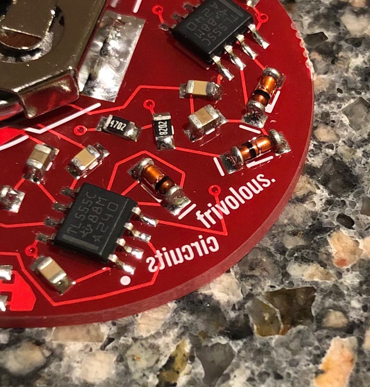
First, you'll note that there's not a perfect 45 or 90 degree angle anywhere on the thing.  In fact, there are even some traces with ACUTE ANGLES. 😱😱😱

There's a single word backwards on the bottom silkscreen! 😘

We used mini-MELF diode packages just because they're cylindrical and love to roll off the table and can be hard to grip with tweezers. 🥰

I mean, who does this with traces? 😍

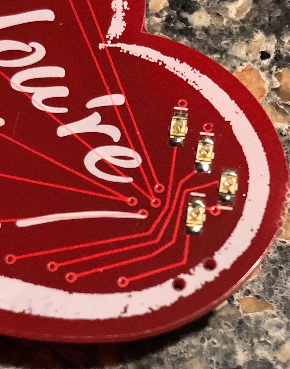
We purposefully left reference designators off of the silkscreen.  Guess you'll have to refer the assembly diagram files to match components to their places.

However, in spite of all that, we kind of think this board looks cool and we're stoked with how the graphics came out.  And who doesn't love some 555 timer shenanigans?  We're using one timer to make a low frequency, about 1 Hz, pulse train with a about a 25% duty cycle.  We're using the other 555 timer to create a continuous roughly 10 Hz pulse train.  The low frequency timer's output is hooked up to the high frequency timer's RESET pin, so the high frequency timer output is on only long enough to let 2 pulses out.  The result is a twice-per-second heartbeat-style pulse that's used to blink the LEDs.  

💓💓💓

Of course, we recognize that not everyone loves blinky things.  So we have a "solid on" switch that bypasses the timers, and just runs the LEDs straight off the battery voltage.  We also have an ON/OFF switch because we don't actually hate you _that_ much.

Happy Valentine's Day, all!

PSIHateYou-Schematic.pdf

Schematic for PS - I Hate You. Helpful for assembly.

Adobe Portable Document Format - 141.00 kB - 02/17/2021 at 20:41

Preview
Download

PSIHateYouFlyer.pdf

Flyer that comes with the kits, showing color-coded components and reference designators. Helpful for assembly.

Adobe Portable Document Format - 495.71 kB - 02/11/2021 at 23:57

Preview
Download

PSIHateYou-Assembly.pdf

Assembly Prints for PS - I Hate You. Refer to these to find out which components are soldered where. Helpful for assembly.

Adobe Portable Document Format - 228.79 kB - 02/11/2021 at 01:49

Preview
Download

  • 1
    Unpack Your Kit & Download/Print Assembly Diagram

    Your kit has color-coded components and a flyer with the color key.  We've given you some extra resistors, capacitors, and LEDs, so you may have left-overs when you're done.  Go to the files section of this project and download or print the assembly diagram.  You may also want to cross-reference components with the schematic.

    You'll note we did not print reference designators on the back.  This was purposeful, just to make the kit a little more pesky.  But it's good practice - not all circuit boards have enough room to mark reference designators.  So think of it as building your surface mount troubleshooting and assembly skills!

    Here's how to figure out which components go where:

    • Understand your component values.  The components are all color-coded.  You can match them to the colors on the flyer to figure out their values.  Or, if you have a multi-meter with sharp probe tips, you can poke right through the tape and measure resistance and capacitance directly.  Also, the resistors actually have their resistance marked on the top if you have magnification or good enough eyes to see it!  The leftmost 3 digits are the resistance, and the digit on the right stands for the number of 0s after.  It's always in ohms.  So "1000" means 100 ohms, "1203" means 120,000 ohms (or 120k ohms).
    • Understand your reference designators.  We've been SUPER NICE and put the reference designators for the resistors, capacitors, and diodes on the color card flyer.  You can also look at the schematic, and match up the values with reference designators.
    • Figure out where each component goes.  Look at the assembly diagram, which shows you the reference designator for each component's position.  Match up the reference designator, value, and position, and start soldering!
  • 2
    Start with the 555 timers

    Which solder/flux should I use?  Lead-based solder will be easier to learn with, but lead-free is totally fine too (and better if kids are handling the solder, and more eco-friendly).  We prefer to solder SMT components with water-soluble flux because it's more aggressive and wets out the solder much better, enables you to hit the solder with the iron a few times before it's gone and you get crystallized/cold joints.  BUT BE SURE TO CLEAN IT OFF WHEN YOU'RE DONE.  Water-soluble flux is more aggressive and can corrode boards if not cleaned off.  It is also slightly conductive and will affect the function of your final circuit.  Our next favorite is RMA (rosin mildly activated), and our least favorite for SMT work is no-clean.  But if that's all you have, it's OK!  Don't worry about it, just use it.  More important is having a small diameter solder, to more easily control the amount applied.  We like using 20 mil (0.5mm) or smaller diamter.  We also love using flux pens, it's great for adding just a small bit of flux to a joint to reflow a cold one.

    Now solder your 555s!

    Note that these are directional!  The line on the IC (chip) marks the "top" of the chip, pin 1 will be at the top left.  The top of the chip is also noted by a "U" shape on the silkscreen (under the chip in these photos).  Also, pin 1 is denoted by a dot.

  • 3
    Next, solder all of the resistors

    Be sure to check with the color chart and assembly diagram to figure out which value goes in which position.  We recommend keeping your resistors and capacitors in the tape, and only pulling out one value at a time as you're ready to solder it.  This keeps them from getitng mixed up on your bench!  

    If you're soldering two kits at once, use the same technique.  Solder all resistors of one value on both boards before going onto solder the next value.

    We have given you one extra resistor of each value, in case you accidentally send it flying!  The key is to hold your tweezers in a relaxed grip, with just enough force to hold onto the component. 

View all 12 instructions

Enjoy this project?

Share

Discussions

RW wrote 02/12/2021 at 19:27 point

Nice, I don't know if it's irritating me more that you used the correct form "you're" instead of seizing the opportunity to put "your" or that you used two 555s instead of a 556, although if that was deliberate, I salute you.

  Are you sure? yes | no

Alpenglow Industries wrote 02/12/2021 at 21:32 point

Hahaha!!!!  I was actually thinking of the Your/You're thing yesterday and agree, I totally missed an opportunity.  Though that might have been too much and pushed me over the edge.  😆  Yeah, the double 555s was deliberate - I thought the more components I had, the messier the layout could look.  :)  

  Are you sure? yes | no

Dan Maloney wrote 02/12/2021 at 18:36 point

I hate that I love this. Or I love that I hate it? Either way, nice work.

  Are you sure? yes | no

Alpenglow Industries wrote 02/12/2021 at 21:32 point

Thank you!  <3

  Are you sure? yes | no

sjm4306 wrote 02/11/2021 at 13:05 point

You monster!!! Rofl, jk but in all seriousness this board sets off my ocd like crazy!

  Are you sure? yes | no

Alpenglow Industries wrote 02/12/2021 at 00:21 point

Haha!  Yeeeeeees, mission accomplished!  😆  Glad you like it!

  Are you sure? yes | no

Similar Projects

Does this project spark your interest?

Become a member to follow this project and never miss any updates