 Frank Adams
My Instructable "Battery Powered Raspberry Pi in Repurposed Laptop" shows how to make two different battery charger boards for 12.6 or 16.8 volt LiPo packs. The first board uses a Max1873 with an ATtiny microcontroller to monitor the charging parameters (see below).
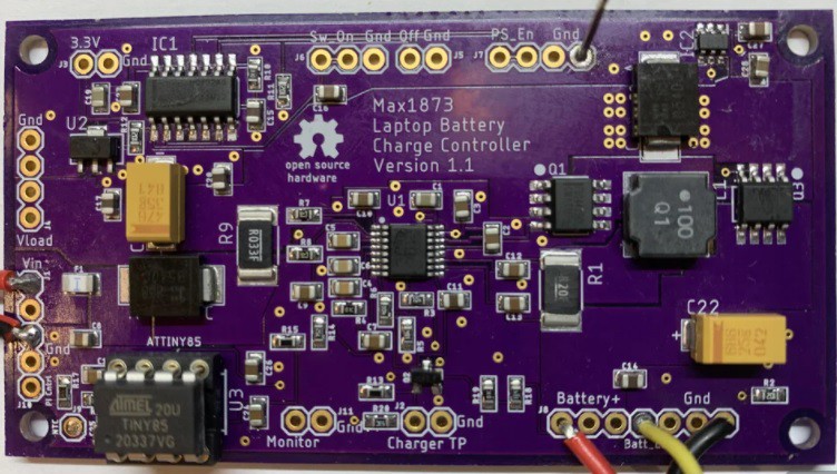
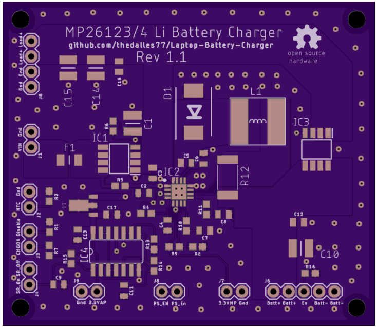
The Max1873 board works great if you want to write your own code for total control but it adds complexity to the project. The second battery charger board uses an MP26123 or MP26124 from Monolithic Power Systems. These chips will pre-charge a dead battery, stop charging when full, monitor battery temperature, and limit the total charge time without any assistance from a microcontroller. The MP26123/4 chips also include the main switching FET inside the package which reduces the layout complexity. The assembled MP26123/4 board is shown below.
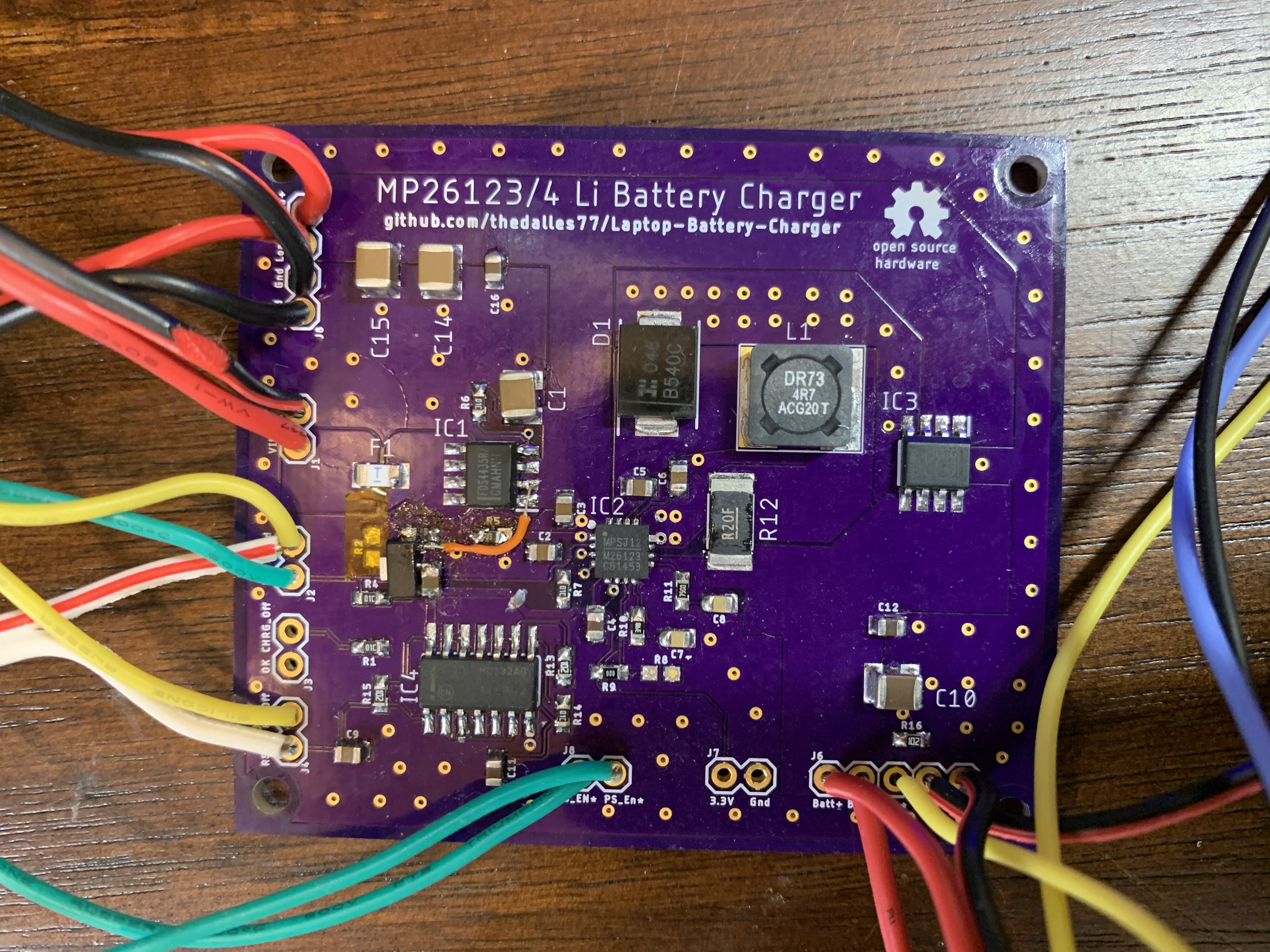
I used the typical application and evaluation board schematics from the MP26123 and MP26124 data sheets to design this board. The part values that need to be changed for the different battery configurations are shown in the following schematic. The Eagle schematic file "MPS_Charge_Controller.sch" is available for download in case you want to modify the design.
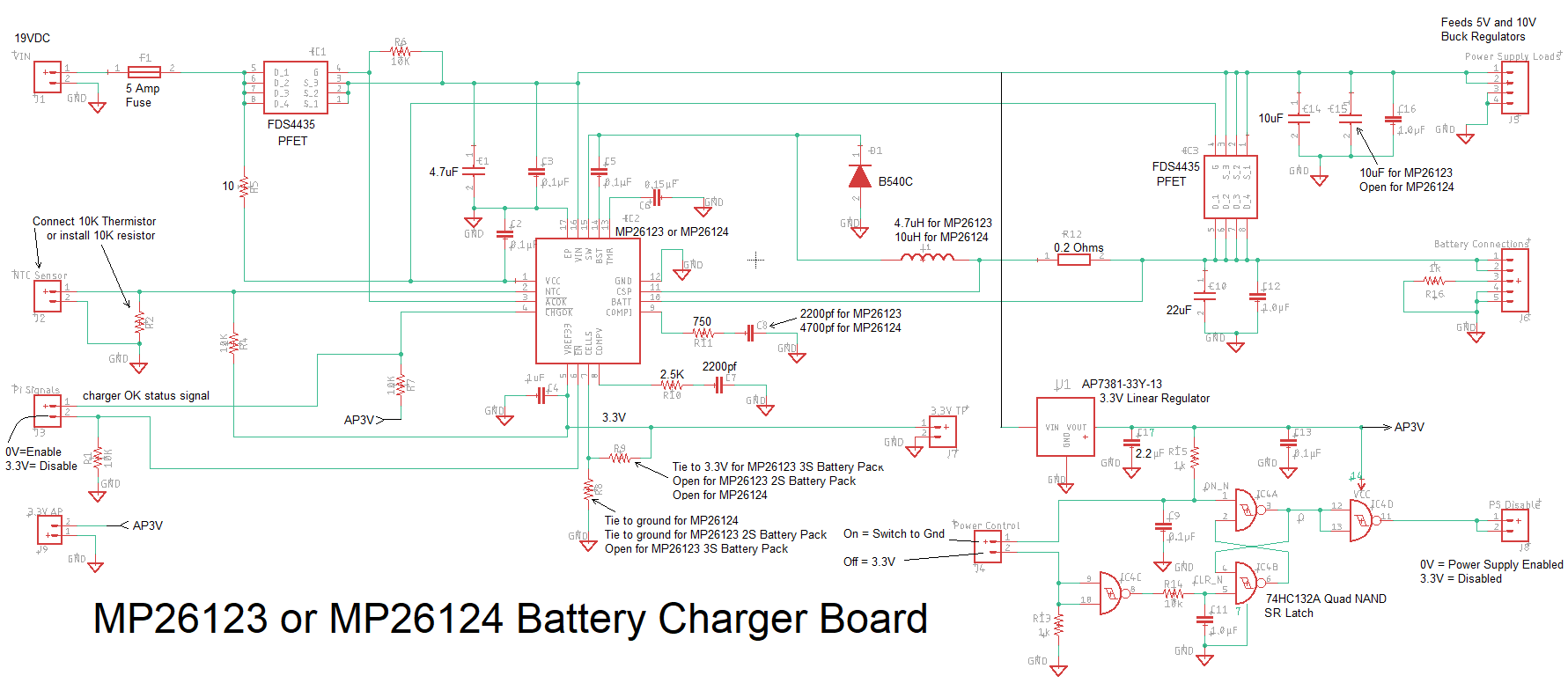
The MP26123/4 chips do not reduce the charge current in order to limit the input current but there is a 5 amp slow blow fuse on the board as a fail safe. Instead of the typical Schottky blocking diode on the input, I use a PFET to reduce heat. There is also a PFET instead of a diode to "Or-Tie" the battery to the load without the usual 0.4 volt diode drop. This is important because the voltage from a nearly empty 3S battery pack is barely enough for the display backlight to keep working. The MP26123/4 board feeds the LM2596 buck regulator loads with either the battery voltage or the 19 volt input. There are no voltage dropouts when the 19 VDC input is unplugged or plugged in. The enable pin of the MP26123/4 is brought to the card edge and can be driven high by the Pi to shut down charging if necessary.
A simple SR latch is always powered in order to enable the buck regulator loads when the laptop's push button power switch is engaged. This latch is powered from a 3.3 volt linear regulator sourced from the battery or 19 volt wall supply. The current draw from the battery when the buck regulator loads are disabled is 315 µamps. Adding in the internal self-discharge of the battery pack at 2% per month plus the protection circuit at 3% per month will cause a fully charged 58 watt hour 11.1 volt battery to be drained in 324 days. If you are not going to use the laptop for some time, pull out the battery pack to cut the discharge in half.
The MP26123/4 will perform a precharge if the battery pack voltage is below 3 volts per cell. The precharge time is limited to 30 minutes at 10% of the full charge current. If the battery voltage rises above 3 volts per cell within 30 minutes, the charge current increases to the full charge level which has been set at 1 amp by resistor R12. The MP26123/4 is rated for up to 2 amps of charge current but I didn't want to push it too hard. When the battery voltage reaches the maximum level (4.2V x number of series cells), the charger transitions from constant current mode to constant voltage. The charge current will drop until it reaches 10% of the full level, causing the charger to shut down to avoid trickle charging.
The maximum charge time is set at 4.5 hours with 0.15uf capacitor C6. Once you know how long it takes to charge your battery pack, you can adjust this capacitor value per the formula in the data sheet. A 10K NTC battery thermistor can be connected to the MP26123/4 to shut down charging if the temperature gets too hot or too cold. Using a standard 10K NTC table, the high temperature turn off is approximately 40ºC and the low temperature shut off is approximately 11ºC. If you don't connect a thermistor, you must add a 10K resistor to ground to simulate room temperature.
The "CHGOK" status signal from the MP26123/4 will go low if it is charging normally. It will go high for the following conditions; end of charge, NTC fault, time limit, thermal shutdown, disable pin, Vin under voltage.
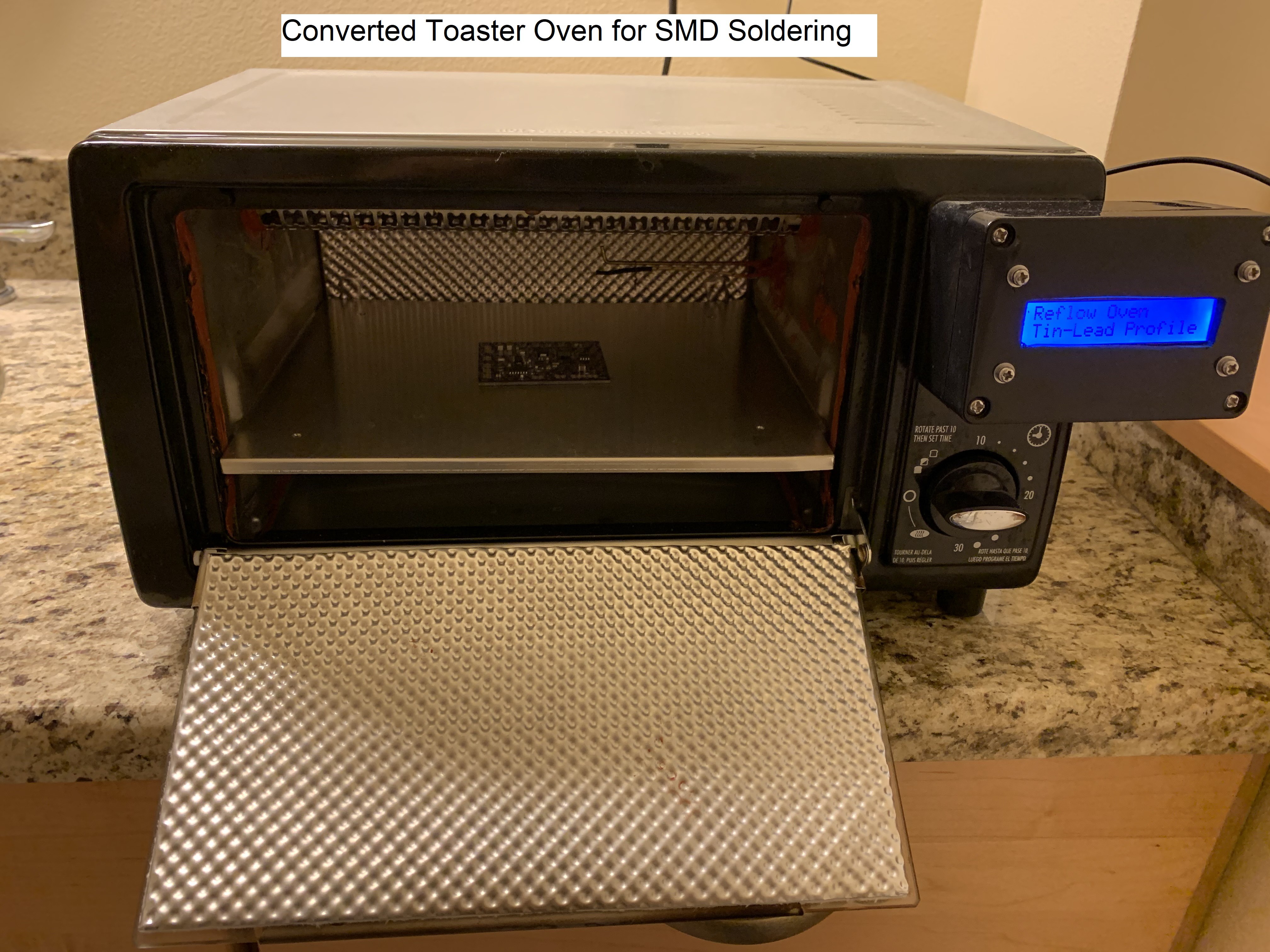
There are some drawbacks to using the MP26123/4 chips. They can only be used to charge lithium cells rated at 4.2 volts maximum. Older laptop battery packs that use 4.1 volt cells and new battery packs with 4.35 volt cells should use a charge controller like the Max1873 that can adjust its maximum voltage level. The MP26123/4 only comes in a leadless package making it more difficult to hand solder. I used the DIY reflow oven shown below to flow solder the MP26123 board. A hot air rework station could also be used to assemble the board.
The circuit board trace widths were designed to handle at least 3 amps with no more than a 10ºC rise in temperature. Several trace width calculators and graphs were checked, based on 1oz copper, 63mils board thickness, 4.8 in^2 board area, and a ground plane on the back side. The 4mm worst case from the IPC-2152 nomograph seems very conservative compared to the 2.25mm result from an IPC-2152 calculator and the 1.37mm result from an IPC-2221 calculator. The smallest power traces on the board are 5mm wide. This excludes the traces that neck down to the MP26123/4 pins to carry 1 amp to the switching FET.
My first board used the 3.3 volt output from the MP26123 to power the latch but it's only alive when the wall supply is plugged in. The updated board design includes a separate 3.3 volt linear regulator to keep the latch alive when not plugged in. The OSH Park rendering for the new board is shown below. It is 62mm x 54mm.
Upload the Eagle layout file "MPS_Charge_Controller.brd" to fabricate at OSHPark.com. Three boards will cost about $26 with USPS shipping. To fabricate the board at JLCPCB.com, use the zipped Gerber file "MPS_Charge_Controller_2021-02-23.zip". Five boards will cost about $10 with standard (slow) shipping. I applied no-clean Tin-Lead solder paste to the pads with a syringe followed by clean up with a toothpick. A better method is to use a stencil from OSHStencils.com.
Test Results:
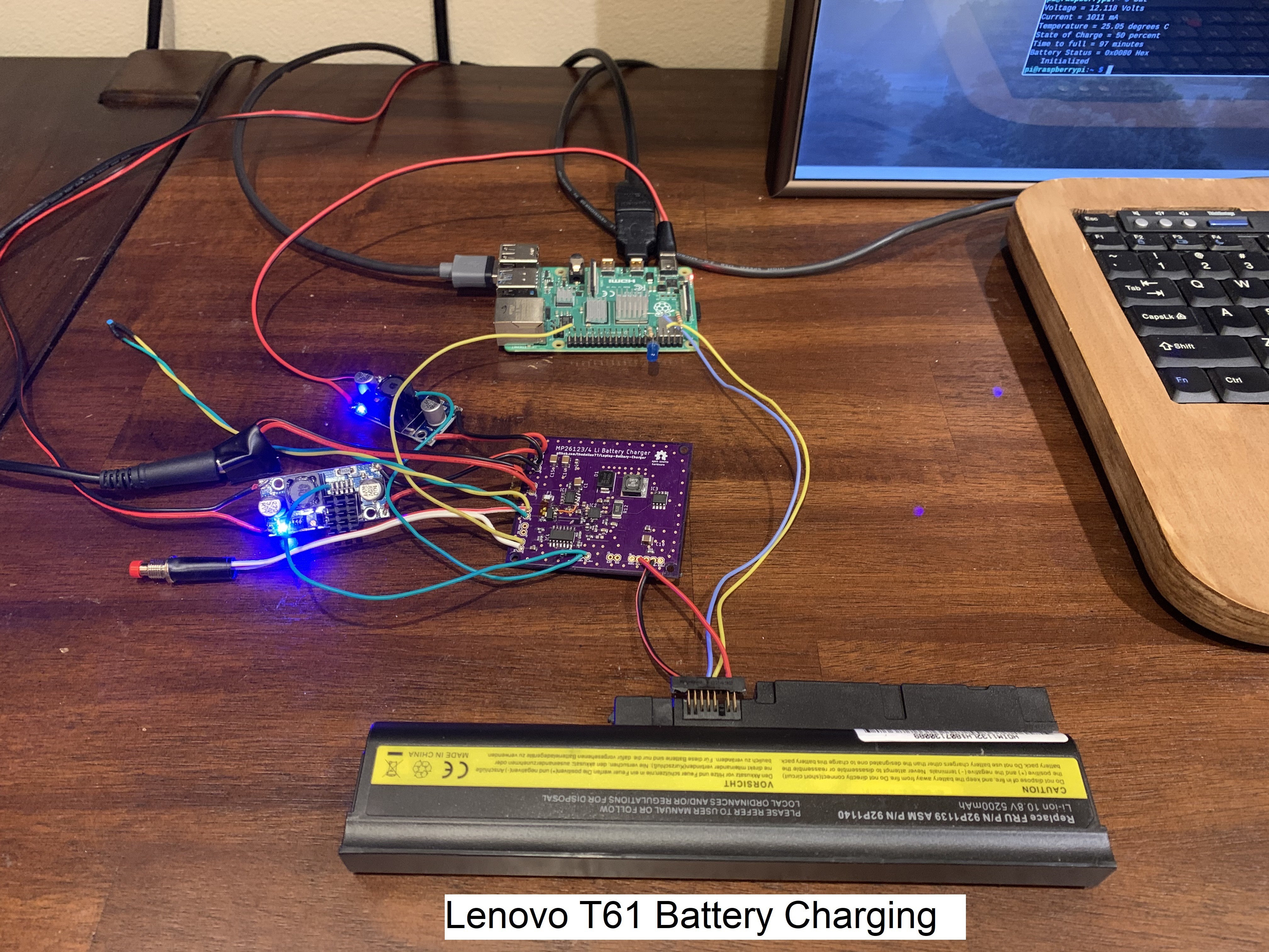
This picture shows my test setup with the MP26123 charging a 3S2P battery from a Lenovo T61. The push button switch sets the SR latch that enables the 5 and 10 volt LM2596 buck regulators. These power the Raspberry Pi and video converter card on the back of an old laptop monitor. Charging starts when the 19 volt DC plug is connected and can also be controlled with the enable pin at the board edge.
The plot below shows the test results for an MP26123 charging a 3S2P battery pack from a Lenovo T61.
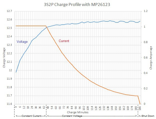
Initially the MP26123 was in constant current mode at 1 amp for the first 45 minutes. The charger transitioned to constant voltage mode, holding just under 12.6 volts while the current slowly dropped. At 183 minutes, the current dropped to 100ma and the MP26123 terminated charging. I confirmed the precharge mode when I tried to charge a 3S2P pack that measured 6 volts. The charge current stayed at 100ma but the voltage stopped rising at 7 volts, causing the MP26123 to terminate charging after 30 minutes. I opened up the battery pack and found two cells were stuck at 0 volts.
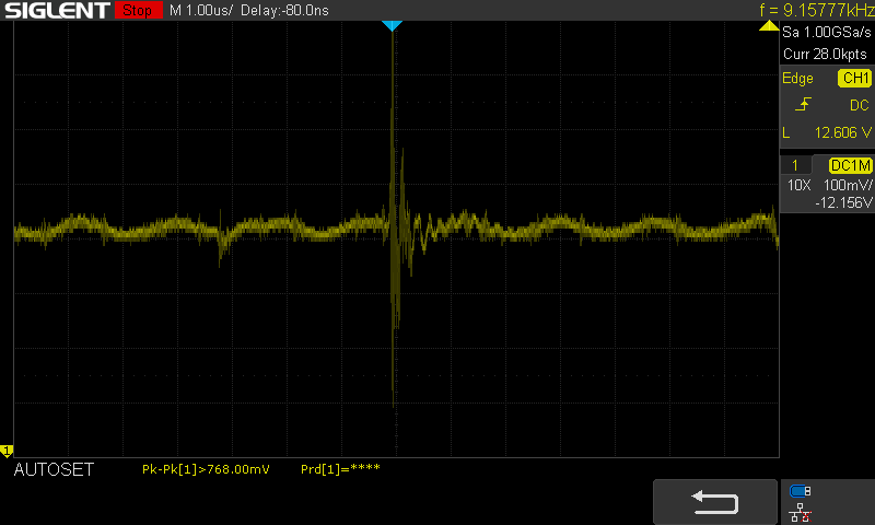
The 600KHz ripple on the battery voltage from the MP26123 was measured at less than 50mv p-p as show below. The large switching spike is from the 19 volt DC wall supply.
Load Switch - If your loads do not have enable control signals or they draw too much current when disabled, you will need a load switch like the one shown below.
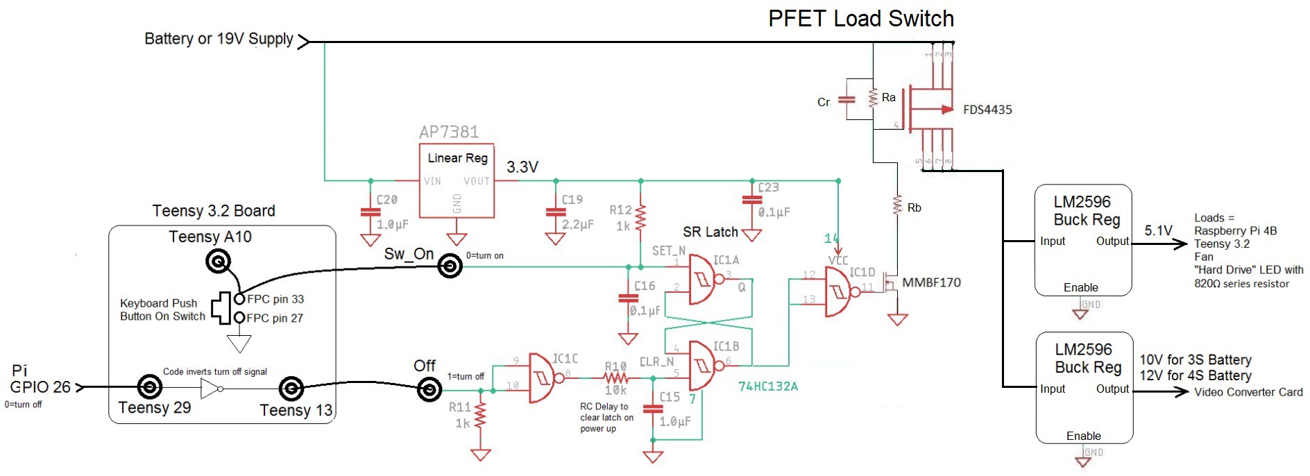
The FDS4435 P-FET will cut power to the loads when its gate is pulled to the source voltage (battery or wall supply). When the SR latch turns on the MMBF170 N-FET, the P-FET is turned on and supplies current to the loads. TI application note SLVA716A describes various discrete component load switches including the one shown above. The resistor and capacitor values can be adjusted to give some degree of in-rush current limiting. The writeup by PowerCTC, section 2.1 gives the equations for the resistors and capacitors.
My Instructable describes how to use the Pi to bit-bang the SMBus clock and data signals to the battery in order to read the status registers. A cleaner approach is to use the CP2112 USB to SM Bus bridge circuit (shown below).
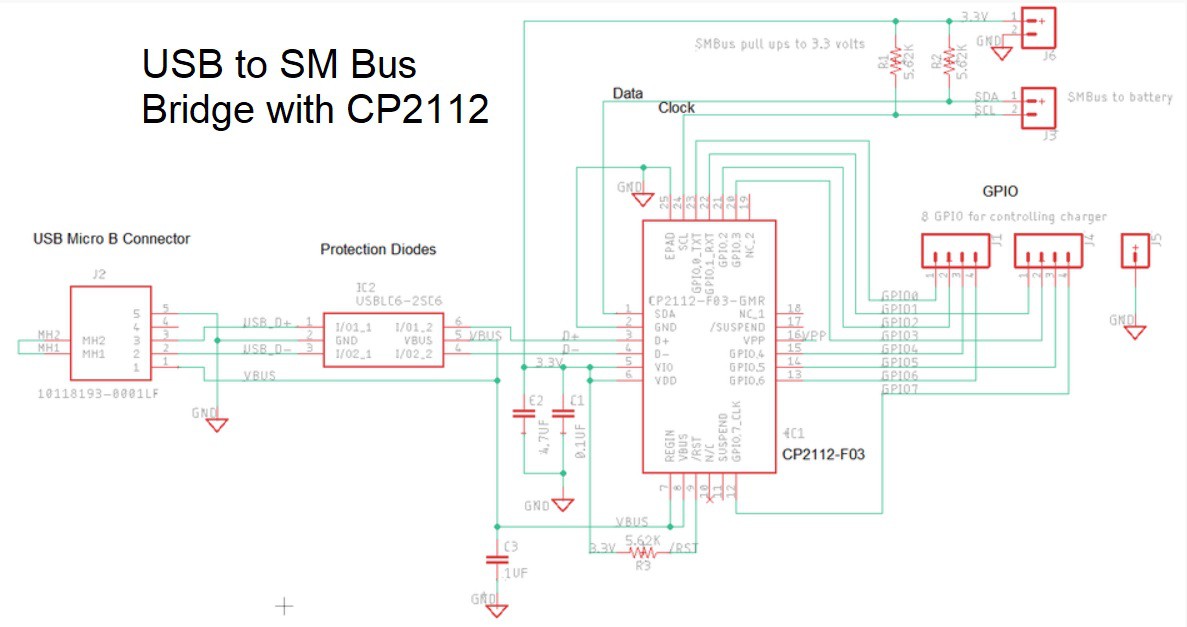
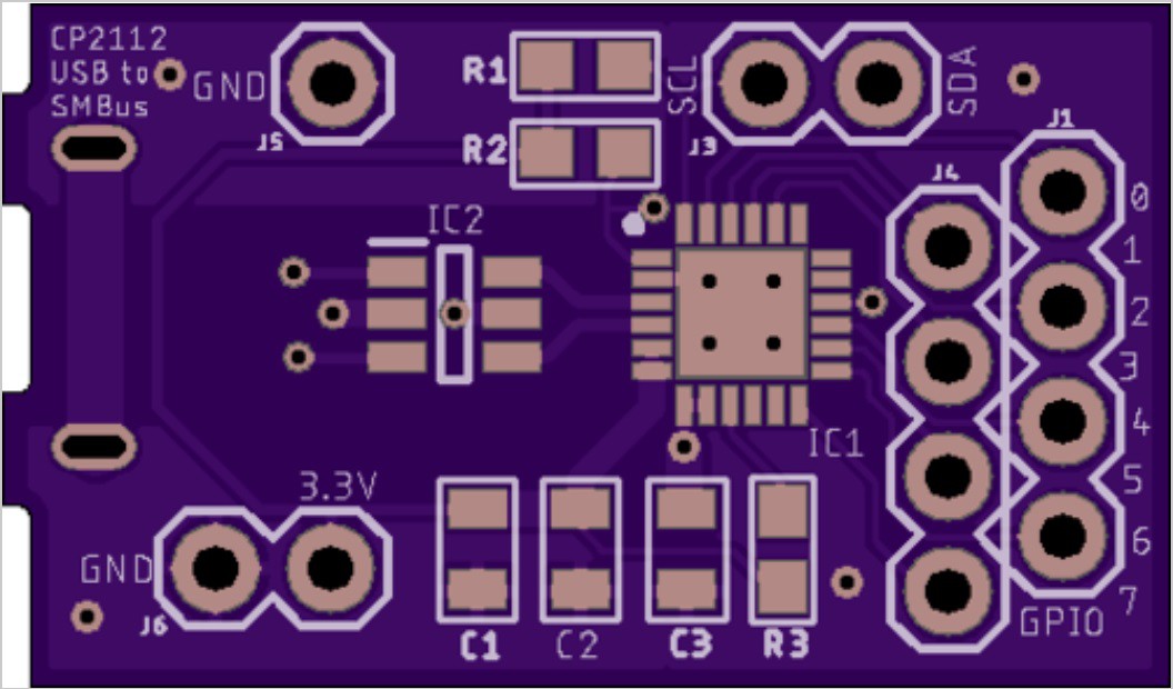
The Eagle schematic and layout files for the CP2112 board are at my repo. I have forked and modified Nick DaDemo's C code that reads the battery registers via the CP2112 using a Windows 10 PC. Silicon Labs offers a CP2112EK evaluation kit for $29 for those that don't want to solder a leadless quad flat pack.
Let me know if you have any questions, comments, or corrections.