Timo Birnschein
-
Progress bars, verify, and other menu items
03/22/2021 at 00:35 • 0 commentsToday, I spent some time making major changes to the code. I really wanted more control over what's happening when when, I also wanted to make it a bit more versatile and also safe.
I added
- Wizard guided flow
- the ability to restore the eeprom from an existing binary file
- an option to verify what has been written to the eeprom
- fixed a bug with passwords shorter than seven characters
- added the ability to select the i2c bus on the beaglebone black
- added option to remove the password completely or chance to a new one
- added status bars for the read, write, and verify operations
The entire workflow of one session can be seen here:
EEPROM Tool - Crack your favorite laptop - hopefully without breaking it...
Author: Copyright 2021 - Timo Birnschein


Please select task: restore EEPROM from file: type <restore>, or read, modify and write system EEPROM: type <modify> (default is <modify>)

What i2c bus / SMBus would you like to use? Default is <2>:

Selecting I2C bus 2

Press Enter to read EEPROM contents...
Reading from EEPROM...
Reading EEPROM: |██████████████████████████████████████████████████| 100.0% Complete
Writing binary to file...  eeprom.bin
Extracting and translating password: hallo
Checksum of password as read from eeprom:  0xa5
Confirmation passcode (should be the same): hallo
Checksum of re-entered password as read from eeprom:  0xa5
Calculating own checksum: 0xa5

The above password might not be correct as your system might use a different encryption scheme!
If the password does not work, writing a new password also won't work! Only removing it altogether will work.

Choices are: remove existing password from EEPROM or write a new password to the EEPROM
Type <remove> or <new> without brackets and hit enter. If you just hit enter, the program will exit.
remove
Writing and encoding new password:
Checksum added to eeprom:  0x0
Writing confirmation password (must be the same):
Adding checksum to confirmation password:  0x0
Writing binary to file...  eeprom_mod.bin


Do you really want to write to the EEPROM of your computer?
************** THIS MIGHT BRICK YOUR LAPTOP!!! **************
Type:  and hit enter (case sensitive, no brackets!)...
Yes I want to
Writing binary file back into EEPROM, length: 256
Writing EEPROM: |██████████████████████████████████████████████████| 100.0% Complete
Reading EEPROM back for verification...
Reading EEPROM: |██████████████████████████████████████████████████| 100.0% Complete
Writing binary to file...  eeprom_verify.bin
Verifing EEPROM: |██████████████████████████████████████████████████| 100.0% Complete
Verification completed. EEPROM seems good. No guarantees!

Done. Bye.
I tested this using my 256 byte 24C02 instead of flashing my laptop a hundred times. This also led to me changing the address the script accesses to only 0x57 which is where the supervisor password is located. Eventually, I would like to blow this up even more by reading and writing the entire 24RF08 again but for only the supervisor password that's not required.
I still don't know where all the other passwords and features are. Unfortunately, there is no nicely documented summary available - at least not as far as I know. If someone has one, please let me know. We could make this into a fully configurable toolkit if we wanted to. Similar to the Lenovo service diskette that allows setting serial numbers and owners and the like.
Btw: Code is here now: https://github.com/McNugget6750/x201Password
Maybe at some point I might look into this menu system a bit more: https://www.daniweb.com/programming/software-development/code/309413/console-application-menu-module
-
Demo Time!
03/20/2021 at 01:16 • 0 commentsTo show off how all the pieces work together, let's do a demo on my X201.
Please keep in mind that I do not know if the encoding that is used on my laptop will be the same on any other laptop. So my naive approach to reading and decoding the password might work nowhere else!
However, what always works is deleting the password altogether because it doesn't even require any special knowledge of the checksum as it's simply 0x00.
In the end, there are only two risks involved in this process and I want to make sure these are understood:
- Soldering any wires to your laptop might break it because the solder points are very small, there might be shorts, taking apart a complex device isn't easy or straight forward. Simply put: You can brick your laptop by just opening it up the wrong way and making electrical changes to the system might have side effects we cannot foresee.
- Even reading from the EEPROM can cause a hazard. This is due to the fact that the system accesses the I2C bus every four seconds even when the system is doing absolutely nothing. Without an oscilloscope or a similar device one has no idea when the bus is being accessed. Accessing the bus with another I2C master at the same time will cause data corruption. Something that I did which, in fact, messed up the RFID area in my X201.
But then worst, writing to the EEPROM can definitely brick your device because we have no idea if we're able to write everything back into the EEPROM correctly (yet). And if we don't, the system wakes up broken. This is even worst when one writes to the EEPROM while the host system also intends to access the bus. Data corruption guaranteed!
Having said all of the above, one way to get at least around the bus access every four seconds is to turn the laptop off completely and have it connected to a power supply. For some reason, the Thinkpad's mainboard power is on (anyone have any thoughts on the Intel Management Engine? - leave a comment down below) but no one is accessing the I2C bus at that time! Great news for me, as I can freely read and write the EEPROM.
On my laptop, since I knew I wanted to fiddle around with this further, I broke out my I2C bus into the PCMCIA slot via a simple three pin connector. So I can just plug it in and do whatever I want on the bus. If I hadn't done that, I would not be experimenting with it now.
My setup is simple: I use the Beagle Bone Black (even after many days of research still a terribly documented system and I don't understand why anyone would still use this in time of Raspberry Pi galore - yes, I'm aware of the PRU, I haven't looked into programming those in detail, yet) and connect it straight to my laptop's I2C bus.
Then I fire up the cloud9 IDE and execute my Python project which accesses the bus and attempts to read from it. Since I know the bus is being accessed every four seconds, I have an oscilloscope set up to watch the signal lines. Once an access cycle is over, starting the four second gap, I hit enter to signal the BBB to start the process and read the bios EEPROM. Once read, it will spit out the currently set supervisor password in clear text, create a separate image with a modified, known password, confirm that it calculated everything correctly and then wait for another user input to start writing the new image file back to the EEPROM.
I really didn't want to write junk to the EEPROM so I force the user (me) to type a security sentence to start the writing process. Watching the oscilloscope closely, waiting for the four second gap again, I hit enter once the gap is there. Within milliseconds, the new image is written to the bios EEPROM (only one of the four sections of the EEPROM) and the new password can be entered immediately to unlock the laptop.
Obviously, the EEPROM write step isn't mandatory to unlock the laptop because the script already exposed the originally set super visor password. So once we have that, we can just enter it to unlock the bios. But if the password uses a different encryption, we can use a different command to delete the bios password altogether. Honestly, this is what I should be doing because why would I want to enter anything at all if I don't absolutely have to.
So what's next to do? Well, there are a couple things I really want to implement should I find the time:
- Automatic detection of bus activity via GPIO lines and showing the status on an LED
- Use that detection to time reading and writing automatically within the script
- Option to write a new password or write a blank password via security phrase before writing
- Writing and verifying the EEPROM automatically
- Understanding how Computrace is stored in the EEPROM and allow deactivation of Computrace if active
- Understanding how any other bios password is stored and figure out a way remove or rewrite those as well
- Publish the script without getting sued by Lenovo. :) It's science after all and they definitely know about all of this. The EEPROM has been decoded many times and it's borderline insane that all these techniques still work after so many years even through all the various bios updates. But hey. Access to hardware has almost always allowed a hacker to break the security gates given some time.
-
Different I2C devices with different power states
02/21/2021 at 22:03 • 0 commentsLaptop powered off with power supply plugged in after complete power off with battery out and power supply disconnect:
debian@beaglebone:/var/lib/cloud9$ i2cdetect -r -y 2
     0  1  2  3  4  5  6  7  8  9  a  b  c  d  e  f
00:          -- -- -- -- -- -- -- -- -- -- -- -- --
10: -- -- -- -- -- -- -- -- -- -- -- -- -- -- -- --
20: -- -- -- -- -- -- -- -- -- -- -- -- -- -- -- --
30: -- -- -- -- -- -- -- -- -- -- -- -- -- -- -- --
40: -- -- -- -- 44 -- -- -- -- -- -- -- -- -- -- --
50: -- -- -- -- 54 55 56 57 -- -- -- -- 5c -- -- --
60: -- -- -- -- -- -- -- -- -- -- -- -- -- -- -- --
70: -- -- -- -- -- -- -- --
Laptop powered on, waiting before bios with power supply plugged in:
debian@beaglebone:/var/lib/cloud9$ i2cdetect -r -y 2
     0  1  2  3  4  5  6  7  8  9  a  b  c  d  e  f
00:          -- -- -- -- -- 08 -- -- -- -- -- -- --
10: -- -- -- -- -- -- -- -- -- -- -- -- -- -- -- --
20: -- -- -- -- -- -- -- -- -- -- -- -- -- -- -- --
30: 30 31 -- -- -- -- -- -- -- -- -- -- -- -- -- --
40: -- -- -- -- 44 -- -- -- -- -- -- -- -- -- -- --
50: 50 51 -- -- 54 55 56 57 -- -- -- -- 5c -- -- --
60: -- 61 -- -- -- -- -- -- -- 69 -- -- -- -- -- --
70: -- -- -- -- -- -- -- --
Powered up and booted to Ubuntu
debian@beaglebone:/var/lib/cloud9$ i2cdetect -r -y 2
     0  1  2  3  4  5  6  7  8  9  a  b  c  d  e  f
00:          -- -- -- -- -- 08 -- -- -- -- -- -- --
10: -- -- -- -- -- -- -- -- -- -- -- -- -- -- -- --
20: -- -- -- -- -- -- -- -- -- -- -- -- -- -- -- --
30: 30 31 -- -- -- -- -- -- -- -- -- -- -- -- -- --
40: -- -- -- -- 44 -- -- -- -- -- -- -- -- -- -- --
50: 50 51 -- -- -- -- -- -- -- -- -- -- 5c -- -- --
60: -- 61 -- -- -- -- -- -- -- 69 -- -- -- -- -- --
70: -- -- -- -- -- -- -- --
As can be seen, the 24RF08 chip is now hidden and there, cannot be accessed from the system. I know that the Lenovo Maintenance Disk (yeah, a floppy disk) can write to it. That would mean that Ubuntu or the booting system removes access to the eeprom during boot.
I wonder, though, 0x5C is still there! Maybe the access flags have changed after boot? They do auto-reset after power cycle. Let's take a look!
Shutdown:
debian@beaglebone:/var/lib/cloud9$ i2cdump -y 2 0x5c
No size specified (using byte-data access)
     0  1  2  3  4  5  6  7  8  9  a  b  c  d  e  f    0123456789abcdef
00: ae ae bf bf af af 8f 8f ff ff 7e ff ff ff ff 10    ????????..~....?
10: 26 07 5b 6d d1 00 84 c2 55 60 20 1f ff ff ff 7f    &?[m?.??U` ?...?
Sitting at Ubuntu login:
debian@beaglebone:/var/lib/cloud9$ i2cdump -y 2 0x5c
No size specified (using byte-data access)
     0  1  2  3  4  5  6  7  8  9  a  b  c  d  e  f    0123456789abcdef
00: ae ae 3f 3f 2f 2f 0c 8f 7f ff 7e ff ff ff ff 10    ????//???.~....?
10: 26 07 5b 6d d1 00 84 c2 55 60 20 1f ff ff ff 7f    &?[m?.??U` ?...?
Very interesting indeed! You see the two addresses that can be read from 0x5c. The second line at 0x10 is the ID field used for RFID asset tags and it seems unchanged. There is no reason to change it during boot.
But 0x00 to 0x0F changed a lot! Let's look at the details.
![]()
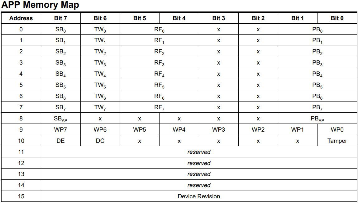
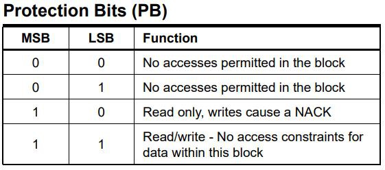
Decoded the above, I can't see why the addresses of 0x54, 0x55, 0x56, and 0x57 would not show in the i2c device scan but what can be seen is that SB6 == b0 and PB6 == b00. This definitely prevents anyone from writing to this section of the EEPROM - here is where the supervisor password is stored. SP6 == b0 prevents one from changing PB6 to something like b11.
![]()
To explain this better: The EEPROM is divided into eight blocks of 128 bytes. Each device address contains two blocks. Hence, 0x57 has two blocks and SB6 signifies the first block of the two, where the supervisor password is stored. So looking at byte 6 in the first line, we see 0x0c == b0000 1100 -> Can't change the bits in PB and PB is set to no access at all.
In addition, the SBx can only be written to '0' and not to '1' making it impossible to change their state via software after the booting OS or bios set them to '0'.
But still, why can't I see those addresses on the bus anymore...?
-
Lenovo Thinkpad Supervisor Password - Gotta have a goal if you want to learn something...
02/21/2021 at 19:58 • 0 commentsSo far, I have only understood where some Lenovo Thinkpads store their passwords. They are located at 0x380 and 0x400. I interpret this as password and confirmation password. These are seven bytes plus one checksum byte. This is not a CRC. It's literally the 8-bit sum of the previous seven bytes. That's it.
Unfortunately, they use an "encryption" method to hide the password and make it non-human readable.
Brute Force
The supervisor password uses some form of encoding. Calling it encryption might push it a little because - at least on my personal X201 Tablet - the encoding is always the same no matter when I set a password. Maybe it will be different on a different Thinkpad? I'll find out when my "new" W530 arrives in the mail.
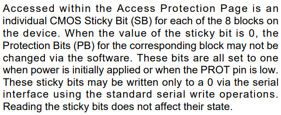
To figure out how the encoding works, I bruteforced my way through all possible characters the Thinkpad accepts for the supervisor password and checked how it is represented in the 24RF08. Thankfully, a complete power cycle wasn't required and the EEPROM was written each time I entered a new password in the Bios' security settings. It looks like this:
![]()
With that in place, I was able to create a map in Python to automatically give me the decrypted password straight from the binary file I read from the EEPROM.
# (Hopefully) Complete mapping between Lenovo encoded characters and the ASCII table
# Technically, the characters aren't needed because chr(hexcode) will give you the same but this is more debuggable and human readable
pwdMap = [[' ', 0x00, 0x00], ['0', 0x30, 0x0b], ['1', 0x31, 0x02], ['2', 0x32, 0x03], ['3', 0x33, 0x04], ['4', 0x34, 0x05], ['5', 0x35, 0x06], ['6', 0x36, 0x07], ['7', 0x37, 0x08], ['8', 0x38, 0x09], ['9', 0x39, 0x0a], [';', 0x3b, 0x27], ['a', 0x61, 0x1e], ['b', 0x62, 0x30], ['c', 0x63, 0x2e], ['d', 0x64, 0x20], ['e', 0x65, 0x12], ['f', 0x66, 0x21], ['g', 0x67, 0x22], ['h', 0x68, 0x23], ['i', 0x69, 0x17], ['j', 0x6a, 0x24], ['k', 0x6b, 0x25], ['l', 0x6c, 0x26], ['m', 0x6d, 0x32], ['n', 0x6e, 0x31], ['o', 0x6f, 0x18], ['p', 0x70, 0x19], ['q', 0x71, 0x10], ['r', 0x72, 0x13], ['s', 0x73, 0x1f], ['t', 0x74, 0x14], ['u', 0x75, 0x16], ['v', 0x76, 0x2f], ['w', 0x77, 0x11], ['x', 0x78, 0x2d], ['y', 0x79, 0x15], ['z', 0x7a, 0x2c]]
# takes an input value and encodes it into Lenovo speak if encodeDecode == 0 # and decodes it into ascii if encodeDecode == 1 # Granted, this is extremely inefficient but I'm not in a hurry. You? def convert_value(input, encodeDecode = 0): if encodeDecode == 0: for r in pwdMap: # look at every entry in our map to check for a match if input == r[1]: return r[2] print(hex(input), " not found while encoding.") return -1 # something went wrong, symbol not found in map elif encodeDecode == 1: for r in pwdMap: # look at every entry in our map to check for a match if input == r[2]: return r[1] print(hex(input), " not found while decoding.") return -1 # something went wrong, symbol not found in map else: print("convert_value(input, encodeDecode = 0) needs either 0 or 1 as input for the encoding direction. You provided: ", encodeDecode) return -1 # something went wrong, function called incorrectlydef read_pwd_from_binary(data): print("\nExtracting and translating password:", end = " ") for i in range(7): print(chr(convert_value(data[0x38 + i], 1)), end = "") print("\nChecksum of password as read from eeprom: ", hex(data[0x38 + 7])) print("Confirmation passcode (should be the same):", end = " ") for i in range(7): print(chr(convert_value(data[0x40 + i], 1)), end = "") print("\nChecksum of re-entered password as read from eeprom: ", hex(data[0x40 + 7])) print("Calculating own checksum:", end = " ") print(hex(calculate_checksum(data[0x38:(0x38 + 7)])))All of this should be self-explanatory due to all my comments and prints in the code.
All I need to do to read the actual password from the last eeprom dump is this:
eeprom.read_pwd_from_binary(eepromDump)It was never easier. No reading miles long forum entries or sniffing around dubious websites to gain access to the password. However, it appears the story isn't always that simple. While doing my research, I found comments about TCPA encryption. So I don't know if my above encoding scheme is that. But I did read about the password also showing up unencoded sometimes. So be aware of that.
If it does, or if the encoding is different from mine for whatever reason, Lenovo invites you to use their backdoor: Simply remove the password altogether and overwriting it with 0x00s.
I implemented and tested both. Create a new password like "test123" or just replace it with seven 0x00s and the corresponding and very complex checksum: 0x00. To do that, I modify the binary we read from 0x57, where the password is stored, and rewrite those said locations 0x38 (8 bytes) and 0x40(8 bytes):
def write_new_password_to_binary(data, password = [0, 0, 0, 0, 0, 0, 0]):
    print("\nWriting and encoding new password:", end = " ")
    convertedPassword = [0] * 7

    for i in range(7):
        data[0x38 + i] = convert_value(password[i], 0)
        convertedPassword[i] = data[0x38 + i]
        print(chr(password[i]), end = "")

    checksum = calculate_checksum(convertedPassword)
    data[0x38 + 7] = checksum

    print("\nChecksum added to eeprom: ", hex(data[0x38 + 7]))

    print("Writing confirmation password (must be the same):", end = " ")
    for i in range(7):
        data[0x40 + i] = convert_value(password[i], 0)
        print(chr(password[i]), end = "")
    checksum = calculate_checksum(convertedPassword)
    print("\nAdding checksum to confirmation password: ", hex(checksum))
    data[0x40 + 7] = checksum

    return data
In execution this would look like this:
# Create a new password and put it back into the binary
newPassword = "test123"
# eepromDump = write_new_password_to_binary(eepromDump, convert_password_to_byte_array(newPassword))
# Alternatively, we simply delete the password from the EEPROM
eepromDump = eeprom.write_new_password_to_binary(eepromDump)
eeprom.write_binary_to_file(eepromDump, "eeprom_mod.bin", 0)
Now, we have a modified binary file and also stored it to disk to be able to double check everything went fine, if desired. All we need to do now is write this new modified binary file to the 24RF08 and restart the laptop. The supervisor password is now gone or set to the value you defined. In the example above it would be either gone or "test123".
Writing to your laptop eeprom is extremely dangerous! Do No Do It unless you know exactly what you do! ALWAYS have a backup of the original file to be able to recover when something goes wrong!
I found some example code to write 8 byte blocks to an eeprom and modified it like so (I would love to give the credits here but I honestly forgot where I found this):
# Write data to eeprom. Again, extremely danger!
################################################################################
# EXTREMELY DANGEROUS! DO NOT USE ON LIVE HARDWARE AND ESPECIALLY LAPTOPS!!!   #
################################################################################
def write_to_eeprom_8(bus, address, data, bs=8):
    print("\nWriting binay file back into EEPROM, length:", len(data))
    # Check number of bytes in the data field
    b_l = len(data)
    # split data into blocks of 8 bytes
    b_c = int(ceil(b_l / float(bs)))

    # Create a list or something from the data to make 8 byte chunks
    blocks = [data[bs * x:][:bs] for x in range(b_c)]

    # Run through the blocks and send each block individually until all blocks sent
    for i, block in enumerate(blocks):
        # Calculate start address for each block
        start = i * bs

        # Send 9 bytes total. 1 byte row address and 8 bytes of data
        # DO NOT USE write_block_data() - very unreliable! Bit errors en mass!
        bus.write_i2c_block_data(address, start, block)
        print(bytes(block).hex(), end = " ")
        print(round((b_c/10*i), 1), end = "%\n")

        # Wait a bit to not overload the eeprom.
        sleep(0.01)
    print("100% - Writing to EEPROM completed!")
And then to do the actual execution I simply do
response = input("\n\nDo you really want to write to the EEPROM of your computer?\n************** THIS MIGHT BRICK YOUR LAPTOP!!! **************\nType: <Yes I want to> and hit enter (case sensitive, leave out the brackets!)...\n")
# # Pretending to write to the eeprom
if response == "Yes I want to":
    eeprom.write_to_eeprom_8(bus, 0x57, eepromDump)
else:
    print("Okey, I won't write anything...\n")
Note that simply pressing Enter doesn't write! You have to enter a phrase to write to the EEPROM to ensure you know what you're doing.
Please note two important things here: I am only writing THE LAST dump that I got back to the EEPROM and not the entire EEPROM. Only device address 0x57, nothing else is being touched! That works here because of how I read the EEPROM. As a reminder:
input("\nPress Enter to read EEPROM contents...\n")
print("Reading from EEPROM...")
eepromDump = eeprom.read_from_eeprom_8(bus, 0x54, 256)
eeprom.write_binary_to_file(eepromDump, "eeprom.bin", 0)
eepromDump = eeprom.read_from_eeprom_8(bus, 0x55, 256)
eeprom.write_binary_to_file(eepromDump, "eeprom.bin", 1)
eepromDump = eeprom.read_from_eeprom_8(bus, 0x56, 256)
eeprom.write_binary_to_file(eepromDump, "eeprom.bin", 1)
eepromDump = eeprom.read_from_eeprom_8(bus, 0x57, 256)
eeprom.write_binary_to_file(eepromDump, "eeprom.bin", 1)
As you can see, I dump a part of the EEPROM into the variable eepromDump, write the 256 byte to a file and then overwrite the same byte array! That's why I can modify the only one section and then write that one 0x57 section back to the EEPROM.
And to be clear: I tested this before I started writing back to my laptop. I detached SDA and SCL from my laptop and plugged in my 24C02 with the address set to 0x57! That way I could write to my own EEPROM and double check my work before I unplugged the 24C02 and plugged my laptop back in.
IMPORTANT ITEM 2:
My laptop accesses this I2C bus periodically every four seconds! IT IS EXTREMELY DESTRUCTIVE AND WILL CAUSE DATA CORRUPTION if you access the I2C bus while the laptop itself is accessing the bus at the same time! I have an oscilloscope attached to the I2C bus to see what's going on and only accessing the bus when the laptop isn't! Please note, I didn't know this during my very first experiments four years ago and destroyed parts of the EEPROM. My RFID area is corrupted and the laptop complains loudly about it at every boot! No Good!
So be careful! Everything at your own risk!
-
Python on Beaglebone
02/14/2021 at 22:48 • 0 commentsThe only time I used Python in the past was an attempt to scrape data from
web-shopswebsites tobuy a graphics card when availablecheck the weather. So my experience is extremely limited and I have to look up pretty much every single function or import or even if-statements when I wanted to use them for the first time. Python is great and powerful but if you are used to C++ it's a bit of a mystery.I must emphasize that Adafruit has deprecated their libraries and none of them function at this point. It appears, Adafruit has abandoned the Beaglebone support completely as this information isn't even available on their website. Only old and very promising looking tutorials that are simply a waste of time to read!
For ease of use, I use cloud9 - Cloud9 as my Beaglebone (link only works if your Beaglebone has a fresh install and is connected to your PC via the Mini-USB cable). It looks like a full blown Python IDE and has all sorts of nice features like system shell, python shell, debugger and I'm sure a whole lotta other things I haven't used, yet. Even some basic type of code completion.
After successful tests on the console reading and writing to my I2C EEPROM, I wanted to recreate some of these functions in python to automate things. SMBus is the library of choice.
from smbus import SMBus
bus = SMBus(2) # select I2C bus 2, default pins are SCL:19; SDA: 20
First, I wanted to read from the eeprom, so I wrote myself a little function
# Read consecutive bytes from the eeprom
def read_from_eeprom_8(bus, address, size=256):
    binary = [0] * size

    for i in range(int(size)):
        # To ensure we can actually read all 256 bytes from the EEPROM,
        # some memories like the 24RF08 require setting multiple page addresses.
        # The 24RF08 is organized in 128 byte pages that must be accessed individually
        # or the page will simply loop.
        # The 24C02 isn't. But it doesn't hurt to do it regardless.
        if i % 0x80 == 0:
            # print("setting new page at ", i)
            bus.write_byte(address, i) # write the new page address to the address counter
            sleep(0.01) # wait a bit to let the new address settle

        result = bus.read_byte(address)
        binary[i] = result
    return binary
The above function is extremely simple. When called, you have to provide the bus object, an address to read and the number of bytes you wish to extract from that device address beginning at 0x00. If the bus and address can be accessed, it will return a byte array then we can then work with.
I then wanted to write dump this to a file so I created another function
def write_binary_to_file(data, filename = "binary.bin", append = 0):
    if append == 0:
        print("\nWriting binary to file... ", filename)
    elif append == 1:
        print("Appending binary to file... ", filename)
    # Open file to dump the EEPROM data into
    if append == 0:
        file = open(filename, "wb")
    elif append == 1:
        file = open(filename, "ab")

    for i in data:
        file.write(i.to_bytes(1, 'big'))
    file.close()
This function takes the byte array, a file name, and whether you want to append the data to the file or rewrite the file. This is important if we have 8-bit addressed eeproms with multiple internal device addresses like the 24RF08.
Now, with that done, we can simply dump the entire eeprom of a Lenovo Thinkpad X201 Tablet using six lines of code (IF YOU DON'T HAVE AN OSCOLLOSCOPE ATTACHED TO YOUR I2C BUS AND YOU DON' T KNOW WHEN THE LAPTOP IS ACCESSING THE BUS, DO NOT DO THIS OR TURN THE LAPTOP OFF WITH THE POWER SUPPLY STILL ATTACHED. SUSPEND OR SLEEP WON'T CUT IT!!)
eepromDump = eeprom.read_from_eeprom_8(bus, 0x54, 256)
eeprom.write_binary_to_file(eepromDump, "eeprom.bin", 0)
eepromDump = eeprom.read_from_eeprom_8(bus, 0x55, 256)
eeprom.write_binary_to_file(eepromDump, "eeprom.bin", 1)
eepromDump = eeprom.read_from_eeprom_8(bus, 0x56, 256)
eeprom.write_binary_to_file(eepromDump, "eeprom.bin", 1)
eepromDump = eeprom.read_from_eeprom_8(bus, 0x57, 256)
eeprom.write_binary_to_file(eepromDump, "eeprom.bin", 1)
Here, I walk through the four addresses of the 24RF08 and write every byte to my binary file. Note, that the last three sections are appended to the original file as indicated by the trailing '1' instead of '0'. This is the full 1Kbyte of data or 8kbit (according to the 08 at the end of 24RF08). If you just plan on reading the 24C02, you can only read one device address and only get 256 bytes. Now, we have a complete EEPROM dump and can play with it.
-
Scanning the bus - be amazed!
02/14/2021 at 18:39 • 0 commentsAfter a fresh installation of Debian on my Beaglebone Black I was greeted with a console interface that had all the essential tools already installed. It's a development platform after all. They provide everything for I2C devices as well. I had a 24C02 EEPROM sitting around, so made it my first target. I set the address to 0x57 in this example - why will be clear in a later entry.
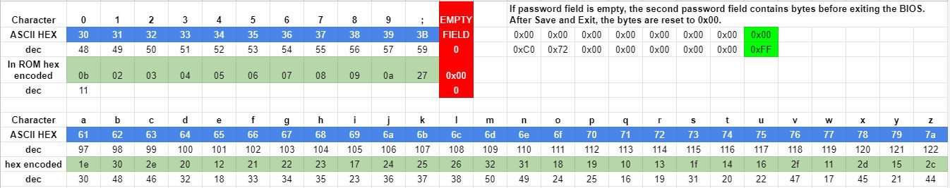
debian@beaglebone:/var/lib/cloud9$ i2cdetect -r -y 2
     0  1  2  3  4  5  6  7  8  9  a  b  c  d  e  f
00:          -- -- -- -- -- -- -- -- -- -- -- -- --
10: -- -- -- -- -- -- -- -- -- -- -- -- -- -- -- --
20: -- -- -- -- -- -- -- -- -- -- -- -- -- -- -- --
30: -- -- -- -- -- -- -- -- -- -- -- -- -- -- -- --
40: -- -- -- -- -- -- -- -- -- -- -- -- -- -- -- --
50: -- -- -- -- -- -- -- 57 -- -- -- -- -- -- -- --
60: -- -- -- -- -- -- -- -- -- -- -- -- -- -- -- --
70: -- -- -- -- -- -- -- --
I was happy to see that the bus worked. I had one device connected to I2C-2 which is sitting on P9_19 (SCL) and P9_20 (SDA) and work right away.
![]()
(source: https://datko.net/2013/11/03/bbb_i2c/)
I ran a couple of experiments with this EEPROM to make sure I can read and write to the various addresses. It's a 2kBit (256byte) EEPROM - not a lot of space. this particular one can be accessed incrementally with a page size of 256byte. That makes, when reading, I can set the address counter to 0x00 and then run 256 consecutive reads and always get the next byte until it rolls over at the end of the page (address 0xFF).
i2cset -y 2 0x57 0x00 // write to the address counter 0x00 i.e. RESET it

ic2get -y 1 0x57 // returns byte at 0x01
ic2get -y 1 0x57 // returns byte at 0x02
ic2get -y 1 0x57 // returns byte at 0x03
I tested this concept on the console before I jump in and write the python code - of which I knew almost nothing about at this point.
You can also simply dump an entire 256 byte chunk of an EEPROM (with 8 bit address space) buy using
debian@beaglebone:/var/lib/cloud9$ i2cdump -y 2 0x57
No size specified (using byte-data access)
     0  1  2  3  4  5  6  7  8  9  a  b  c  d  e  f    0123456789abcdef
00: 21 f8 f8 f8 41 50 21 21 74 20 69 73 20 70 72 6f    !???AP!!t is pro
10: 76 65 20 74 68 61 74 20 79 6f 75 20 68 61 76 65    ve that you have
20: 20 77 72 69 74 74 65 6e 20 32 35 36 20 62 79 74     written 256 byt
30: 65 73 20 69 6e 74 6f 20 61 6e 20 45 45 50 52 4f    es into an EEPRO
40: 4d 2e 20 49 20 64 6f 6e 27 74 20 6b 6e 6f 77 20    M. I don't know
50: 69 66 20 79 6f 75 72 20 45 45 50 52 4f 4d 20 69    if your EEPROM i
60: 73 20 61 63 74 75 61 6c 6c 79 20 32 35 36 20 62    s actually 256 b
70: 79 74 65 73 20 61 74 20 74 68 65 20 74 69 6d 65    ytes at the time
80: 20 6f 66 20 77 72 69 74 69 6e 67 20 62 75 74 20     of writing but
90: 6f 6e 20 74 68 65 20 6f 74 68 65 72 20 68 61 6e    on the other han
a0: 64 20 69 74 20 64 6f 65 73 6e 27 74 20 72 65 61    d it doesn't rea
b0: 6c 6c 79 20 6d 61 74 74 65 72 2e 20 54 68 65 20    lly matter. The
c0: 69 6d 70 6f 72 74 61 6e 74 20 70 61 72 74 20 69    important part i
d0: 73 20 74 68 61 74 20 79 6f 75 20 68 61 76 65 20    s that you have
e0: 77 72 69 74 74 65 6e 20 32 35 36 20 62 79 74 65    written 256 byte
f0: 73 20 73 75 63 65 73 73 66 75 6c 6c 79 21 21 21    s sucessfully!!!
Very handy if you just want to see what the current contents of an EEPROM are. However, it must be said that at no time can two different bus masters access the same bus at the same time. On I2C there is always only one bus master allowed or corrupted data is guaranteed!
To write the above content to the EEPROM, I decided to start with Python.
Hacking a Supervisor Password - With a Beagle Bone
I found myself being intrigued with the low level safety features of my X201. I experimented with the I2C bus and it got interesting...