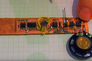
I bought an automatic dog door to let out the dog into the backyard, while avoiding that the cat escape. The door works with a "smart" collar with an ultrasonic transmitter. The cat has learned he can escape via the dog door so I've taken to putting it in one-way mode. This means the dog can come in on her own but I still need to let her out. I've been wanting to come up with a way to open the door remotely to let her out, but the dog door lacks network connectivity. I've been looking for a way to interface to it by reverse-engineering the ultrasonic protocol that the collars use.
0%
0%
Automatic Dog Door Smart Home Interface
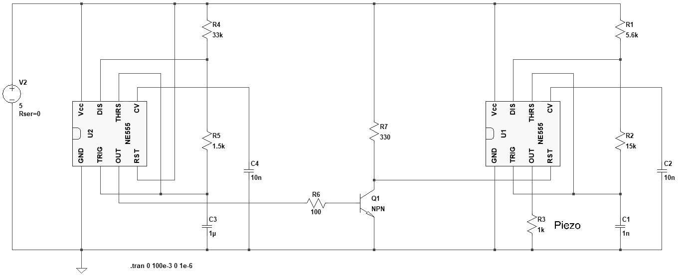
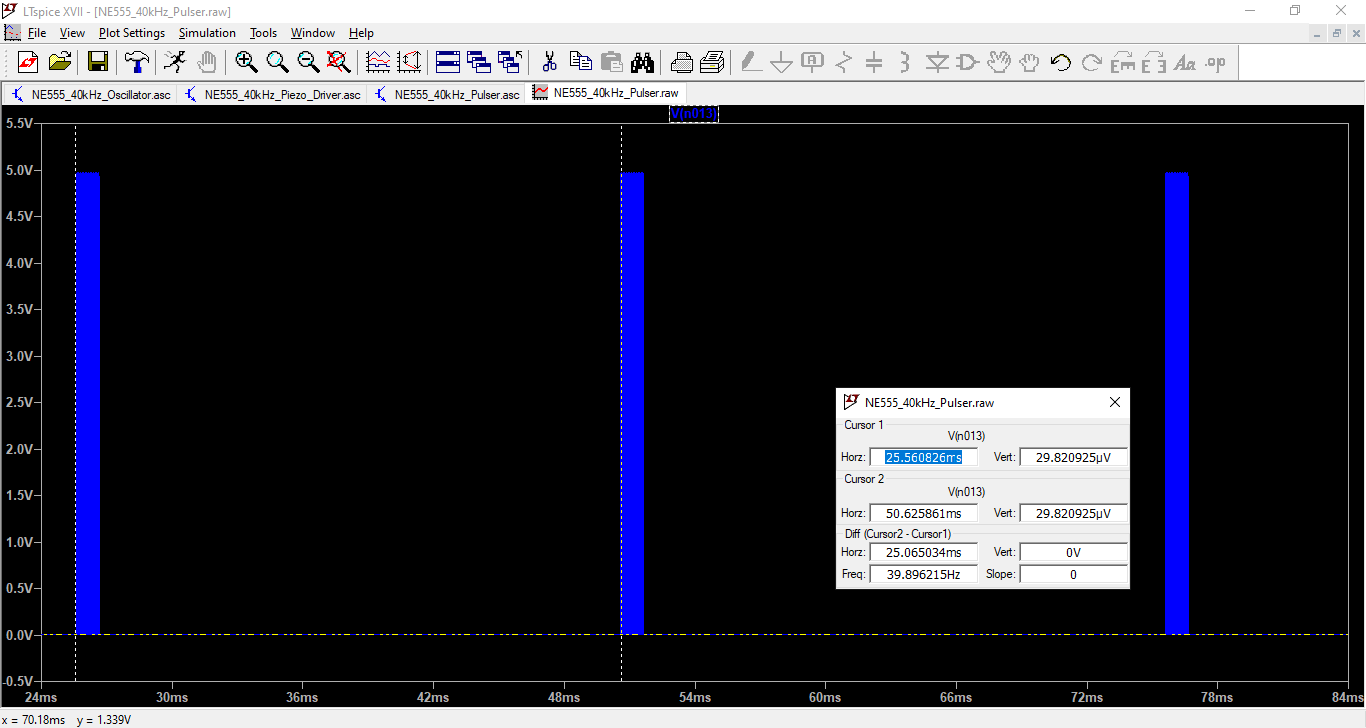
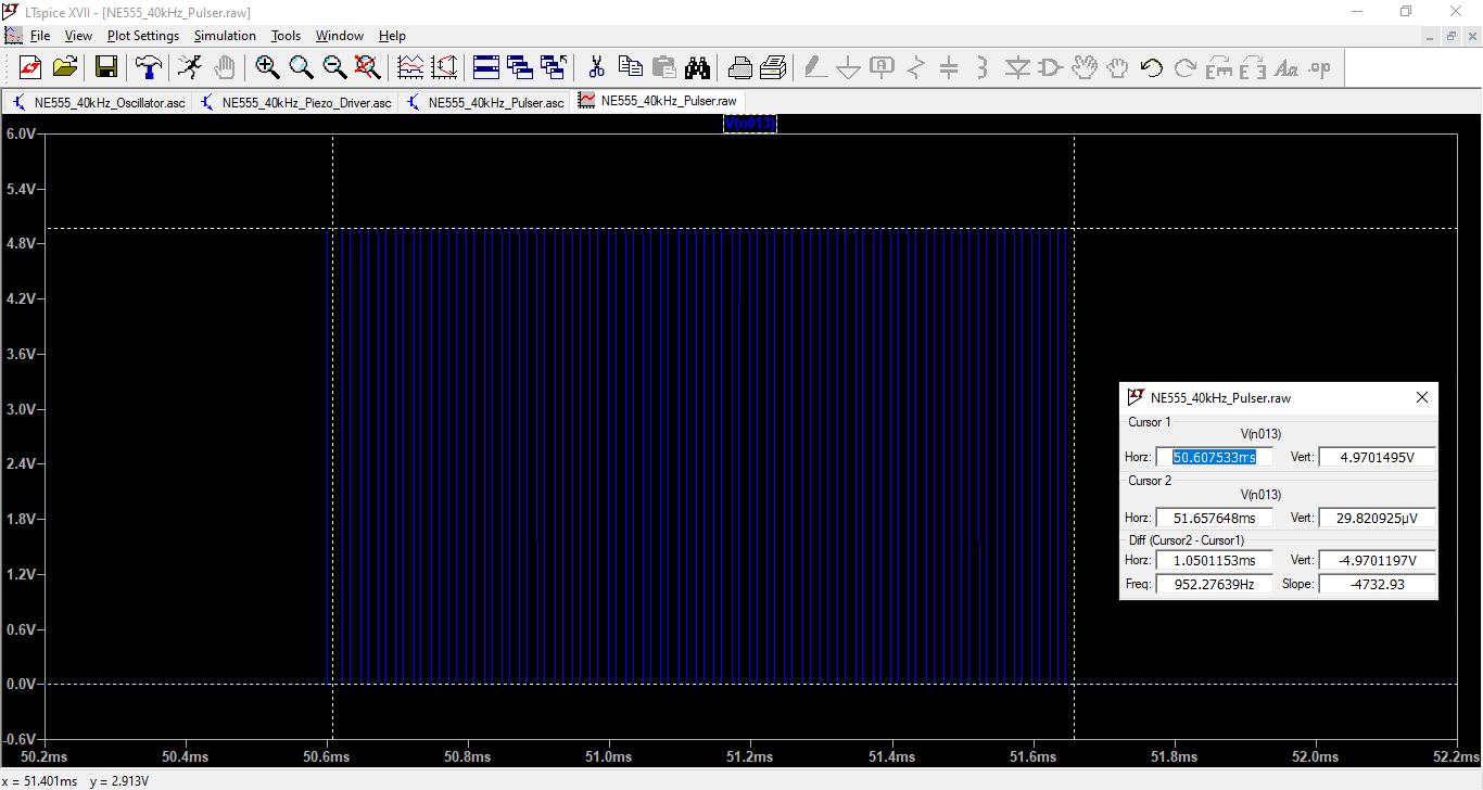
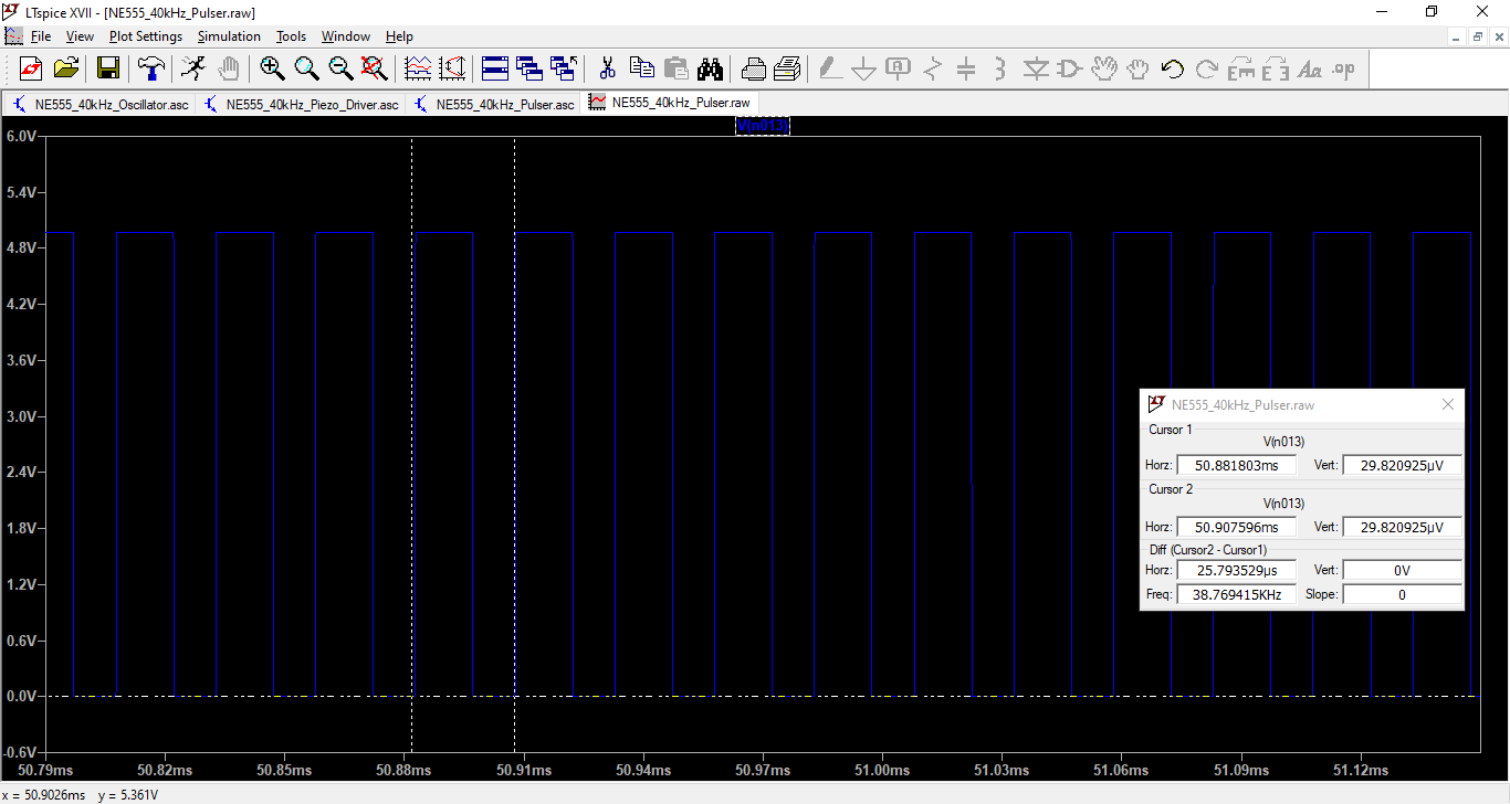
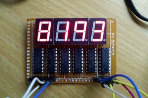
Reverse engineering an automatic dog door
ultrasonic protocol to control it
Become a Hackaday.io member
Already have an account? Log in.
Just one more thing
To make the experience fit your profile, pick a username and tell us what interests you.
Pick an awesome username
hackaday.io/
Your profile's URL: hackaday.io/username. Max 25 alphanumeric characters.
Pick a few interests
Projects that share your interests
People that share your interests
 matseng
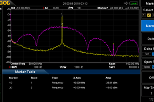
 Ted Yapo
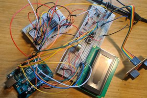
 HummusPrince