 Quinn
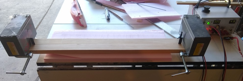
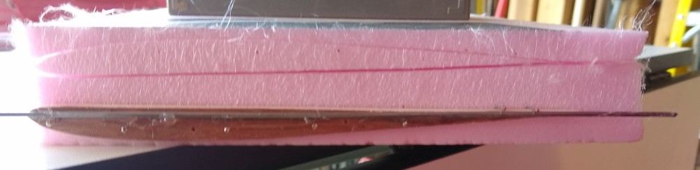
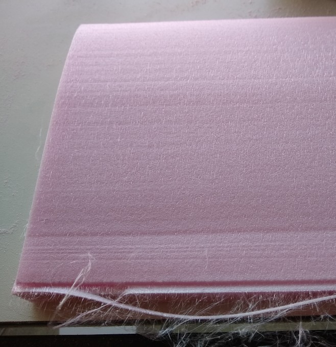
QuinnA hot wire foam cutter is a way to cut through foam. It uses a resistive wire with current running through it to heat up above the melting point of the foam. The wire can then be slowly pulled through the foam to make cuts.
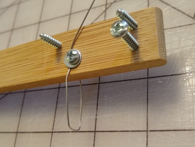
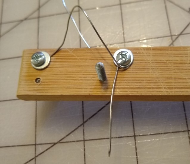
The wire most often used is nichrome, a common wire used in heating. This can be ordered, or pulled out of a forced air electric heating element, such as a hair dryer or some space heaters(look for the coils of wire as some heaters embed this into ceramic for safety). Others have used thin braided stainless steel wire, which they say is stronger. This is available as fishing line leader, making it perhaps more available in retail stores. The most available is steel wire, which can be found at the hardware store. I've used this in the past, though it seems to degrade pretty quickly.
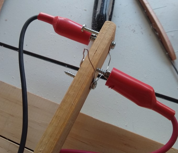
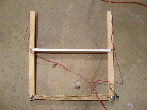
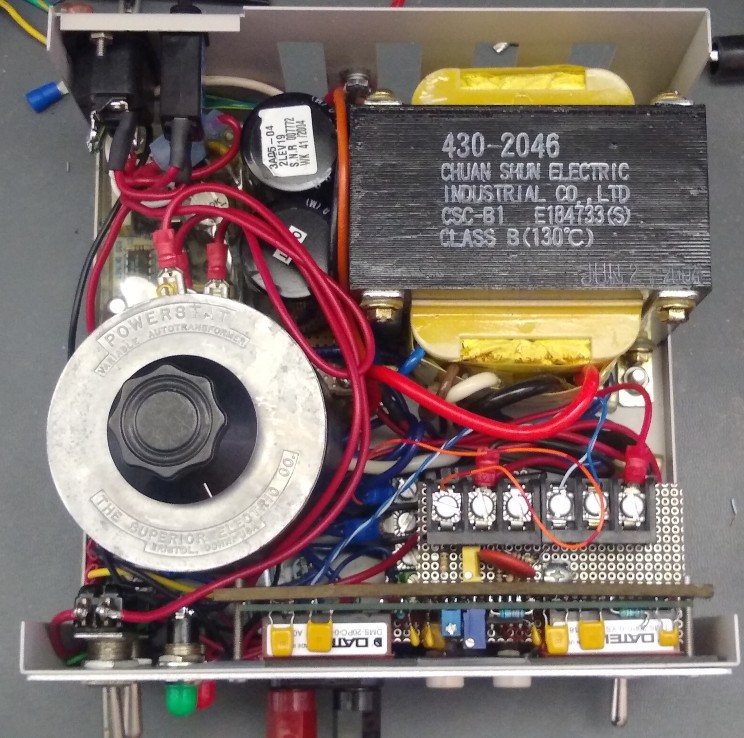
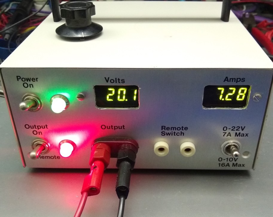
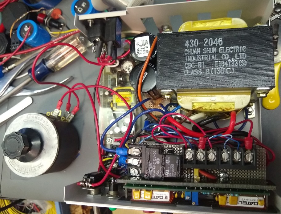
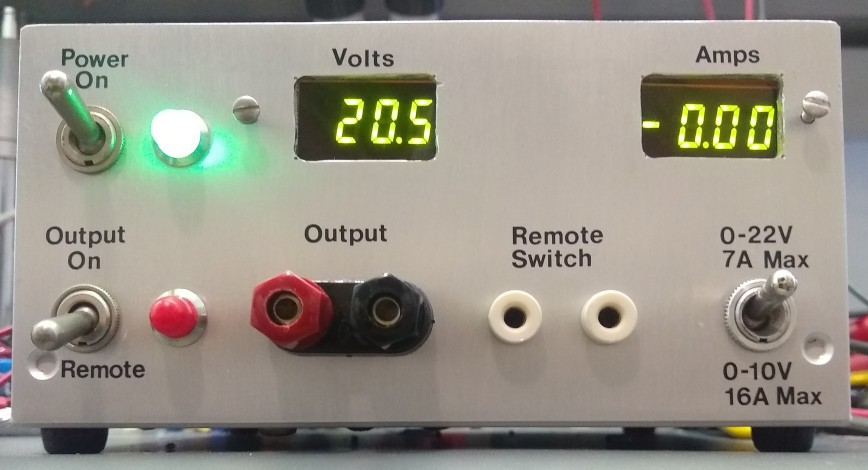
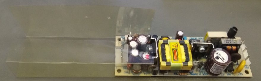
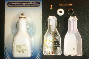
The power supply needs depend on the use case. A simple table type cutter is simplest as the voltage and current needs are moderate. To support long cutting wires as in a bow, somewhat higher voltages are needed. To support rigid wire cutters, low voltage but higher current is needed. The supply developed here is to be capable of all these. A bench power supply can be used directly for this, with the added benefit of constant current, though I don't have a more portable one. A 3 or more cell hobby lipo along with a brushed motor speed control and servo tester is another simple and portable option.
Logs with more information:


 W4KRL
W4KRL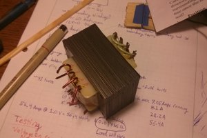

 Paul Andrews
 jbb
jbb