 Quinn
QuinnCase
For a case, I found one I could reuse. It was originally an old parallel printer port switcher. I was never going to need that, so pulled the electronics out to use.
I laid out the front panel with all the connectors, switches and meters, as well as spaced things inside. It's going to be a tight fit, but should work. The variac control will need to go on top, and because it is going to be pretty weighty, I will add a large handle on top as well to easily move it around.
Front Panel
As the front panel already had printing and various holes on it, to make it look nice, I cut an aluminum sheet to overlay it, then cut all the openings through both of them.
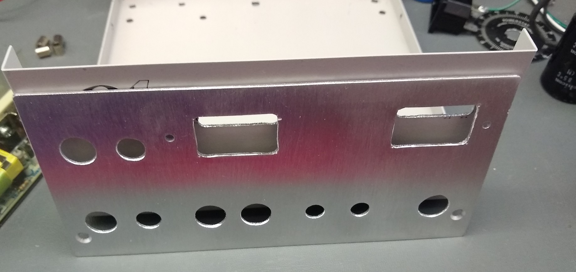
I finished the metal with a simple brushed appearance, by using 150 grit sandpaper all in the same direction.
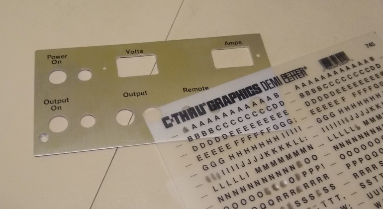
To label everything, I went to the quick solution I've used before and used dry transfer lettering
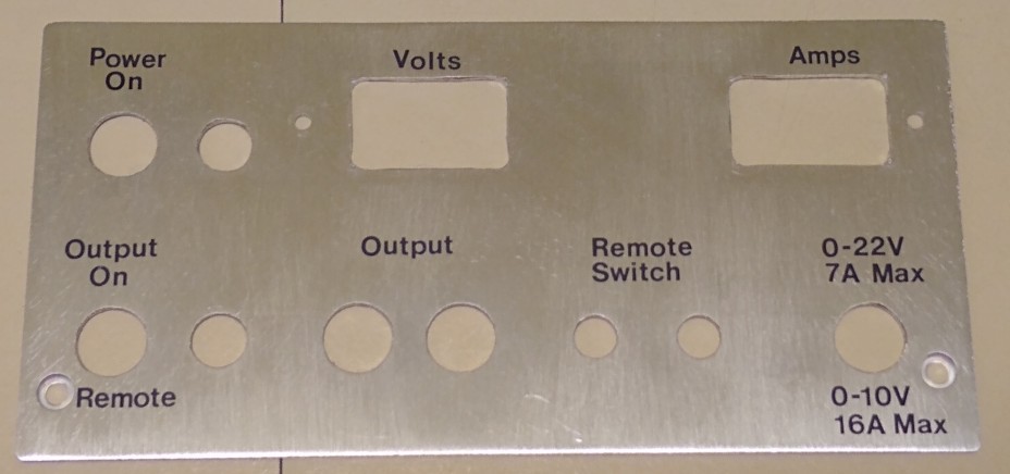
I sprayed several layers of clear enamel over the whole front to protect the lettering, otherwise they would scrape off. The panel is attached simply with the mounting of all the items.
AC/DC Power supply
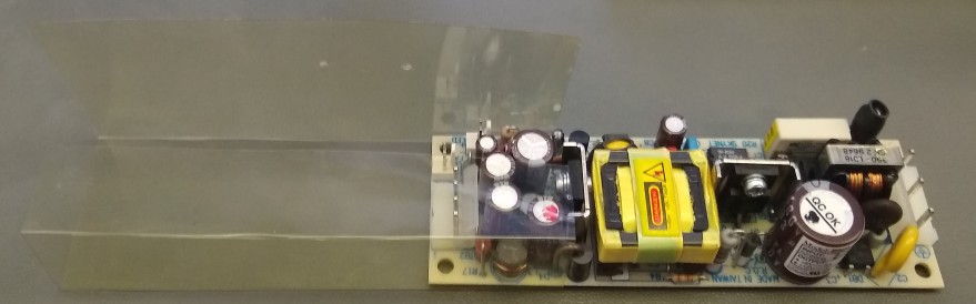
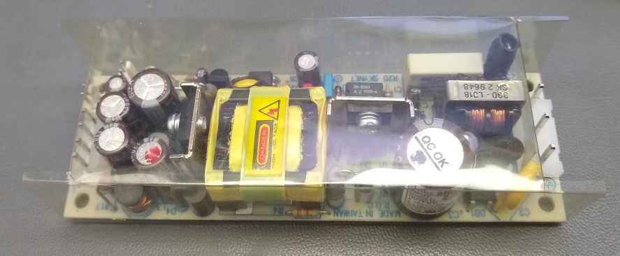
To protect the AC/DC supply for 12V and 5V, I cut and folded a simple box out of clear plastic. This is a common method used in many devices to offer a little extra shielding.
Component layout
To make everything fit, I needed to carefully piece it all together. This required 3D placement as well, because the variac is attached to the top of the case, and yet other parts sit underneath it.
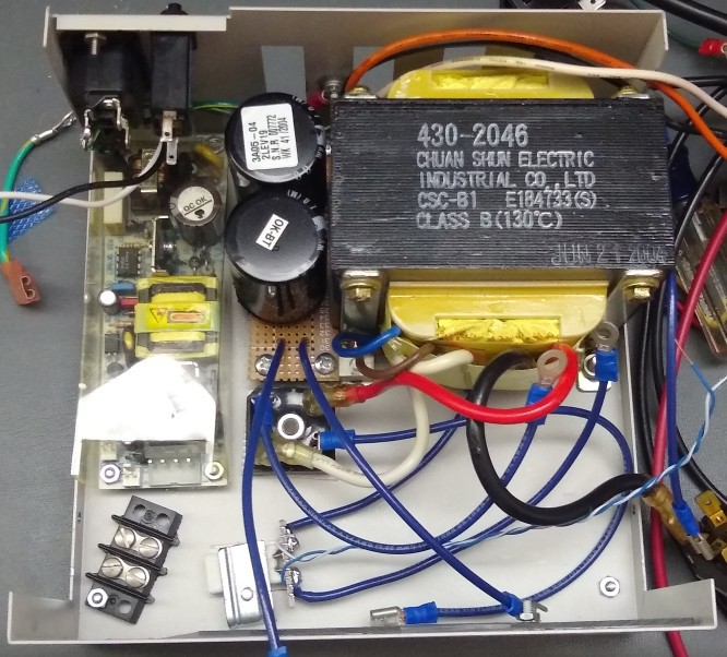
Case Bottom and Back
The main transformer is bolted in the back corner, sharing one of the screws for the rubber feet.
The AC/DC is in the other back corner, sitting on standoffs, and also sharing one of the rubber feet screws.
I mounted an IEC socket and the 1.5A breaker in the back panel.
For grounding, I used one of the studs on the back panel to attach the ground from the IEC socket and to the AD/DC supply input. I needed to scrape the paint off the inside around it to make this work.
For the bulk capacitors, I mounted them on a cut piece of perf board, and mounted it on brackets between the transformer and AC/DC.
The back panel has a bunch of openings that I decided to leave alone. This allows some ventilation, and there isn't really anything live exposed that would be an issue if a finger accidentally reached in.
Up front of the capacitors I mounted the bridge to the case bottom, using a piece of thermal conductive pad to help with dissipation. The steel case isn't going to be the best heatsink, but hopefully will be enough.
Near the front I added a simple lever bracket to clamp the shunt resistor to the case bottom. Again I used a thermal pad to help dissipate heat. This has 14 gauge wires for the main current, but also a twisted pair for the sense lines.
Lastly, I ended up needing a small terminal strip as a couple of the connections were going to have just too many lugs on the same point, so this splits it up, and lightens the load on the PCB as well.
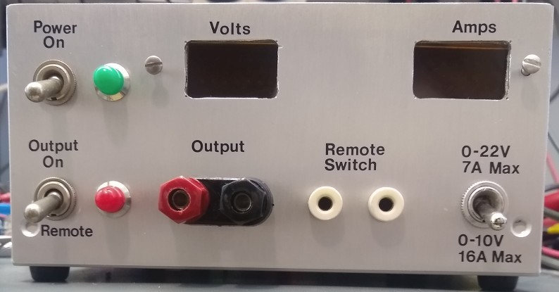
Front panel
The front panel has the various switches, connectors and indicators. These are all panel mount with bolts.
At top left is the input power switch, along with a lamp to indicate it is on.
Below this is a switch which selects for the output to be on, or off/remote. When in the off/remote position, the output will be off, but will turn on whenever the remote switch is turned on. The lamp next to the switch indicates the output is on, regardless of where it is switched.
Top middle is the voltage meter and top right is the current meter. The board I reused didn't have any mounting for attaching to a front panel, so I made a simple clamp with a scrap piece of fiberglass behind it that traps the circuit board between it.
Next along the bottom are the main outputs as binding posts, and banana sockets for a remote switch.
Bottom right is a switch which reconfigures the transformer/rectifier wiring to adjust the voltage/current capabilities. In a higher voltage mode, it can supply up to 22V at up to 7A. In the lower voltage mode, it can supply up to 10V and up to 16A. It can actually supply up to 20A for limited periods as this will cause the shunt resistor and the input breaker to get pretty hot.
Discussions
Become a Hackaday.io Member
Create an account to leave a comment. Already have an account? Log In.