 Jelto
JeltoThe next step is to connect the cells with each other. This means connecting all four cells on each PCB as well as connecting multiple PCBs with each other.
It is very important to only connect cell with the same voltage/charge!
Before connecting the cells, make sure that all cells have the same voltage. I just charged all cells up to 4.2V. The first step was to connect the cells on one PCB. For that I just inserted all the fuses to the fuse holders on each PCB. After populating two PCBs with fuses it was time to stack the first PCBs on top of each other. The electrical connection between both PCBs is done using M3 spacers.
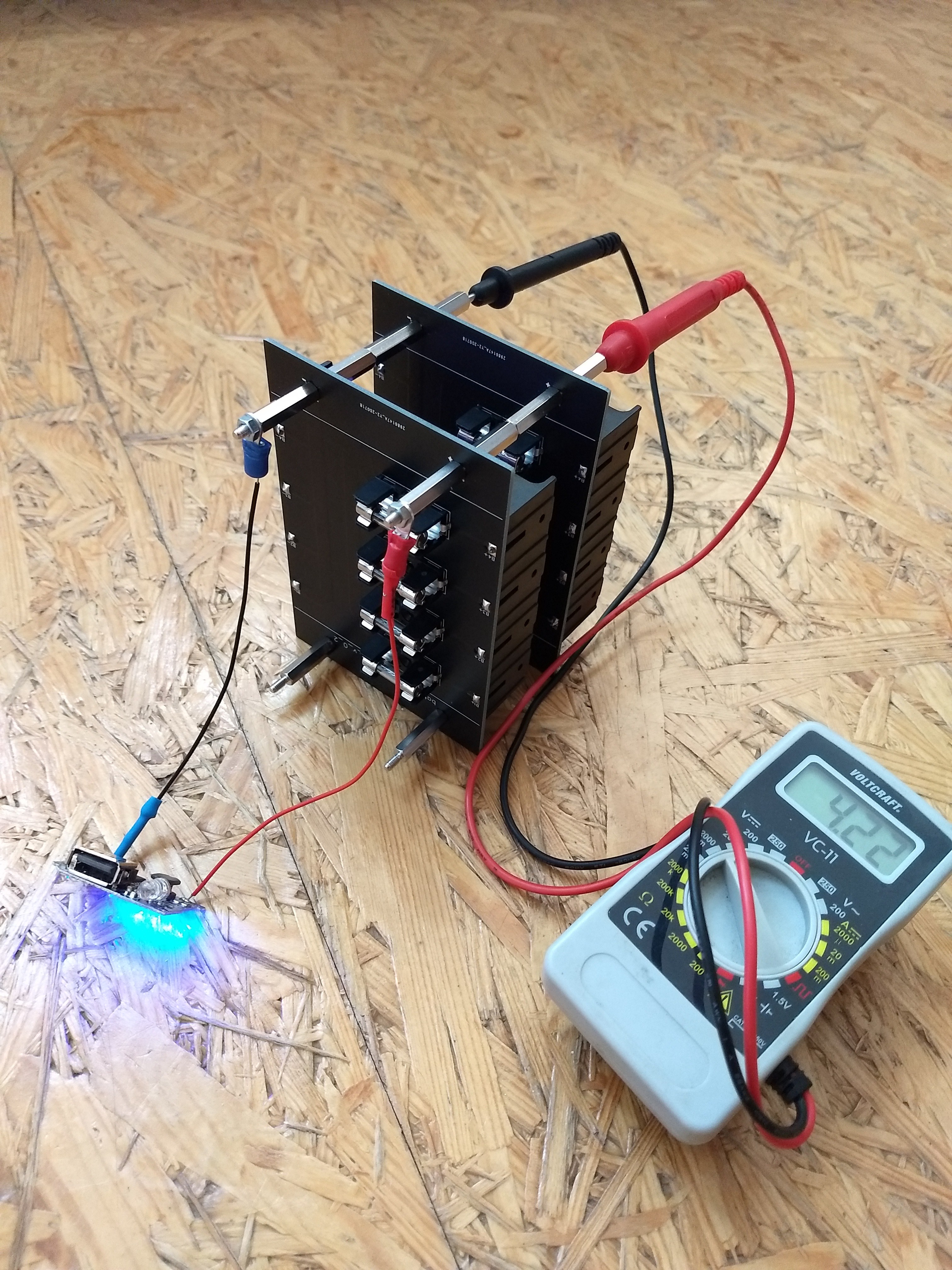
So here you can see the first unit of a working power bank. I added a small USB charging circuit to the Plus and Minus spacers and checked the voltage of the cells using a multi-meter.
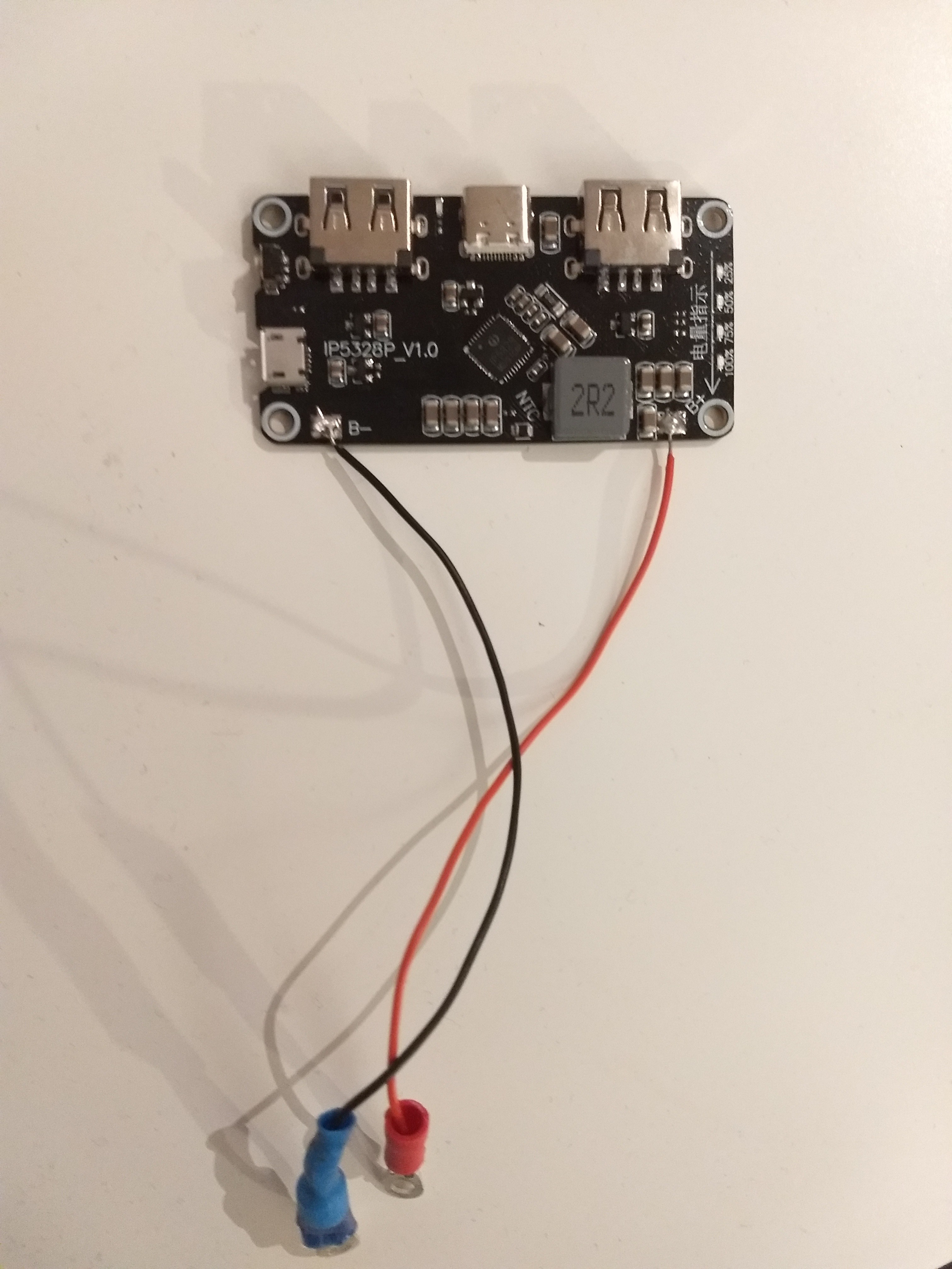
I continued adding additional PCBs to the powerbank. Furthermore I changed the USB charging circuit to a more powerful one. The IP5328P can charge using USB-A and USB-C with up to 18 watts (size of the wire was just for testing).
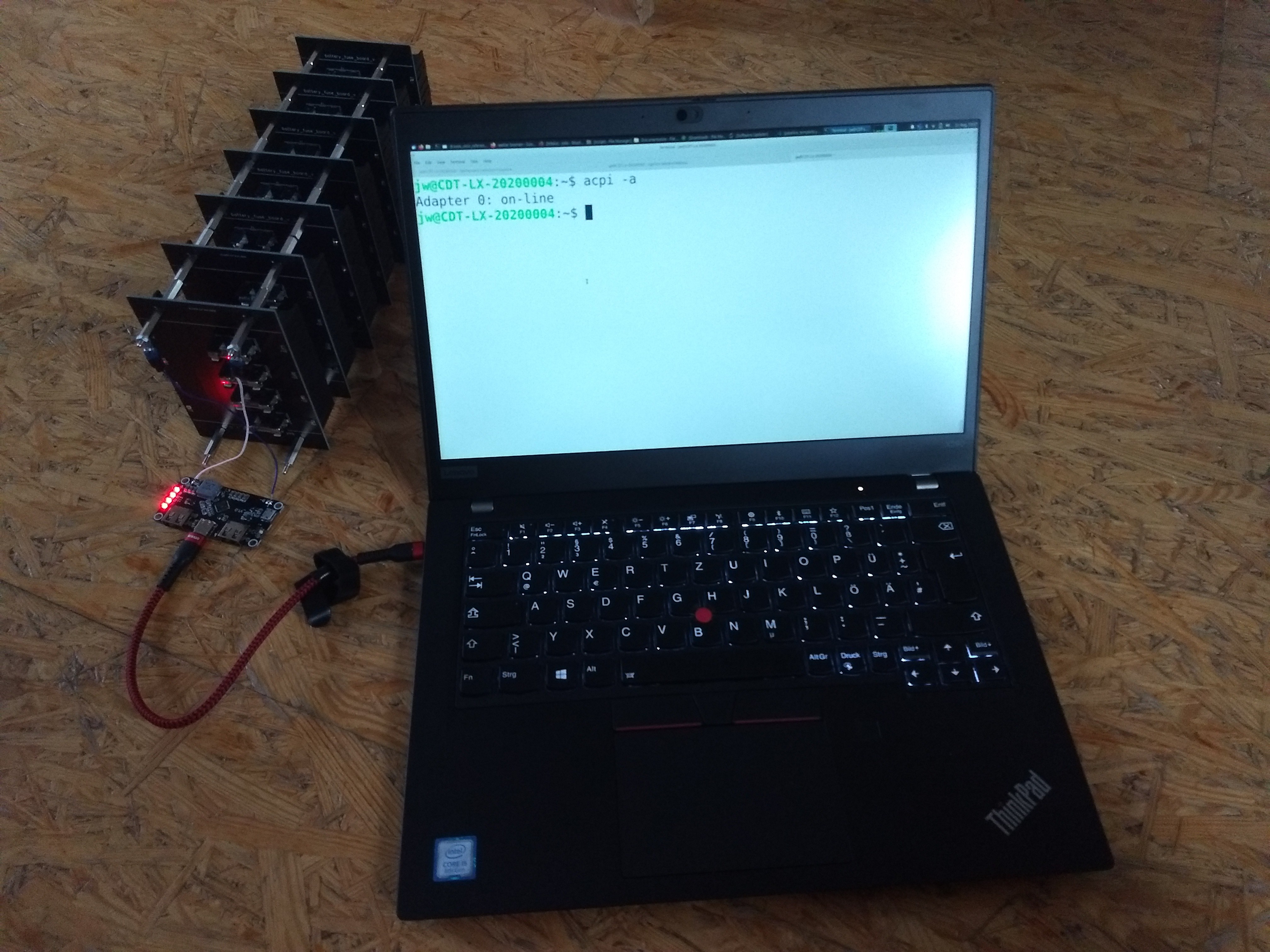
So after stacking all PCBs on each other and adding the USB-C charging circuit I made a first test using a notebook. And it worked, my notebook was charging!
Discussions
Become a Hackaday.io Member
Create an account to leave a comment. Already have an account? Log In.