Close
0%
0%

Battery Operated Hybrid EF95 Valve Amplifier

A custom build of a valve amplifier using two 6AK5/EF95 valves, 4S battery pack with protection, charging module and battery level indicator

Public Chat
Similar projects worth following
I decided to design and make this amp after I was unable to find anything similar. It started out as a simple mains operated amp, I then decided to make it battery operated, this became a bit complicated as I had to come up with a 12v to 100v DC boost convertor, a 4S protection board, a charging module, a battery level indicator and a bluetooth recevier module.

Runtime is about 8 hours depending on the four 18650 batteries. The amp can also be run from the mains.

It has a line in, line out and bluetooth in. Most of the battery opertations and inputs are controlled using relays.

I've use SMD components where possible and audio grade capacitors.

How does it sound, it sounds amazing and clean when running batteries. There is a faint hum when running on mains and no music is playing. As expected the cheap BT module I used is a bit noisy, but everything is modular so can be replaced/redesigned.

This project is modular, meaning some of the modules may be of interest for other projects.
The 100v DC booster can be modified for use with a Nixie clock.
The main amp board is the only thing needed and a 12v supply for listening to music, all the other things are optional.

There was a lot of info that I already wrote on my blog and info is availble on YouTube, see the links on the left for more info.

The valves are EF95/6AK5, so you can use GE JAN 5654W or similar, the valves do the initial amplication before an opamp is used for the headphone amplication.

The battery charging is done via four TP4056X modules, I decided to make this board myself as I believe the modules on ebay are fake or cheap clones, the TP4056X is the latter revision of TP4056. The IC cuts off at 4.2v and can charge at a maximum of 1Amp, I've limited this to 580mA.

To keep the heat low as all four ICs are on the same board I supply an input voltage of about 4.6v and have several heatsinks on the board. The temperature of the board reaches between 50-60 degrees which is acceptable.

Battery protection is done via the ABLIC S-8254 IC, is cuts off if the battery voltage drops below 3V, I designed the protection board so it auto activates/enables when the batteries are connected.

Battery monitoring is done using four LM3914 modules, battery levels are  visually shown for each battery on four LED bargraphs. This module can be calibrated to set the low and high battery voltage.

The high voltage DC boost is done using the UC3843B IC, the circuit takes 12v and boosts to 100v, this can be adjusted at the time of soldering components by changing the feedback voltage divider resistors. In hindsight I could have designed this better with better HV to LV seperation, better choice of mosfet and inductor and getting rid of the extra output filters.

The bluetooth module is the only thing I did not make, I did make a breakout board for it, as I had to use an DC-DC islolator to get rid of the ground loop.

There are two voltage regulators on board, one for charging the battery which is a switching buck convertor and the other is a linear convertor for converting the 4S 16.8v to 12v.

I noticed this was featured on the Hackaday.com site, for some reason I was unable to post my replies.

I'll try and answer some queries here:

No this is not a hifi amp, I've seen many pointless discussions about solid state vs tubes.
I made this for nostalgic reasons, however I was surprised by the quality I use it frequently now. Tubes are meant to add distortion.

I only have Sony MDR-1R and a Master & Dynamic MW60 headphones, both are 32ohms, they play very loud at about halfway up, too loud to listen but I noticed no distortion.

I believe based on other op amp amplifiers this will probably struggle to output to headphones that are >150ohms.


The amplifier is made from the following components:

The main amplifier board, this can be used as a standalone ampliflier, you just need 12DC, line in and headphone out:

Main AMP Board

Next we have the 4S Battery board with the voltage regulators and battery monitoring/switching connections:

4S Battery Board

This is the 4S Protection Board:

4S Battery Protection Board

This is the TP4056X Charging Module:

TP4056X Battery Charger

LM3914N Battery Level Indicator:

LM3914N Battery Level Indicator

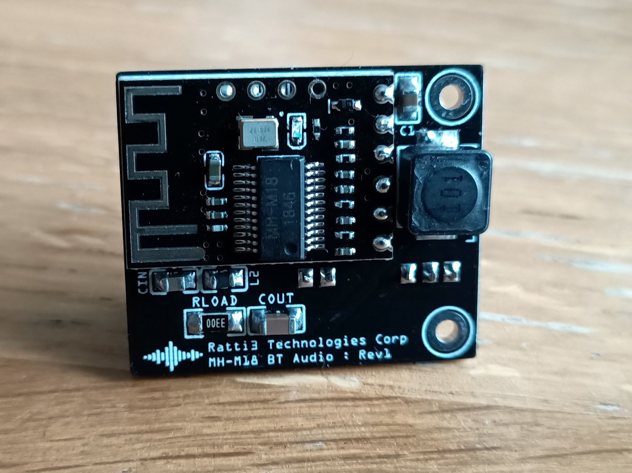
MH-M18 Bluetooth Module:

  • 1 × See EasyEDA project link for BOM

  • 1
    PCBs, components and construction

    WARNING: The project contains a high voltage module, take care when opertating this, it can cause a shock or stop your heart!
    Misconfiguring it can also output 300VDC+.

    The PCB gerbers are available on EasyEDA.

    Explanation of component values are explained in the YouTube videos as well the the Blog, see links to the left.

    I have mostly chosen premium components, it is possible to make this using cheap components from Ebay.

    A lot of the components are SMD, the smallest being the SOD-123 diodes. It takes a bit of patience, steady hand, good flux and a soldering station to get good results. I used a PCB vice to hold the PCB and just use my fingernail to keep a component in place when I solder. I complete each solder in under 0.5 seconds, any longer and my finger will burn.

    Of course no project would be complete if I did not build a prototype, I spend many days testing using a breadboard, and many months designing the schematics and PCBs:

    At certain points of the build stage I tested to make sure the PCB works, here I'm testing the battery charging:

    Testing the battery charging

    I decided to use perspex to make the amp case, I prefer this as I like to see my creation and it's easy to work with. I cut perfectly straight lines using a tenon saw and use fine emery paper to get the smooth finish.

    Perspex clamping

    To make all the mounting holes I use a cheap equivalent of the dremel, the most important thing is to have a precise drill press. I use the Dremel drill press which is compatible with my non Dremel drill.

    Precision drill press

    Once all the PCBs are ready, it's time to start fixing them to the middle layer of the Perspex, all the PCBs have 2mm mounting holes, so it's just a case of making the holes and mounting them. Here is the rear panel PCB which is screwed to the 5mm thick Perspex:

    Rear panel wiring

    All the wiring is done using JST connectors to make it easy.

    JST cables are used for joining all the modules.

    That is all, for me using Perspex made making the case easy. The hardest part was thr design and testing. I make several prototypes on PCB before I fixed all the problems. I think I ended up making the battery protection 6 times because I was an idiot and did not ground myself and damged the mosfets.

View all instructions

Enjoy this project?

Share

Discussions

Dan Maloney wrote 02/18/2021 at 19:10 point

Looks fantastic, I'll check out the videos to hear how it sounds. Nice work, thanks for posting!

  Are you sure? yes | no

Ratti3 wrote 02/20/2021 at 22:55 point

Thanks, I wasn't able to capture the playback in the videos, anyway it would be pointless. The sound is clean and neutral when running on batteries. Changing the OpAmps and Valves makes a difference to the sound (this is something subjective but I notice it). There is a faint hum when running on the mains, you can't hear it when playing music. No hum when running on batteries.

  Are you sure? yes | no

Similar Projects

Does this project spark your interest?

Become a member to follow this project and never miss any updates