Close
0%
0%

Voltage controlled oscillator

Try an analog method

Similar projects worth following
I've been trying to make signals 430-480 kHz without much luck. The digital methods work for certain frequencies related to the main clock. The in-between frequencies require something else. Let's try an analog solution. The microcontroller can control an external oscillator.

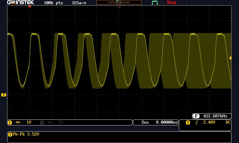
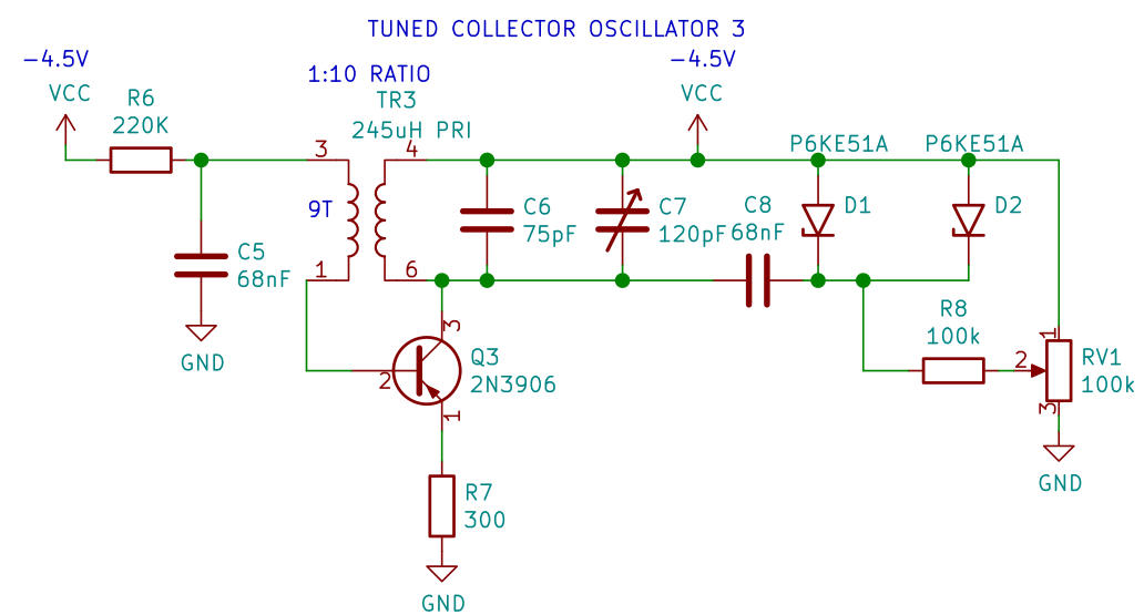
The plan is to make an analog VCO centered around 455kHz.  Then use an ATMEGA or M0 board to control the VCO using an analog output (tuning voltage).  Maybe measure the VCO frequency using a timer peripheral to close the loop.

This project is in several parts.  I'll add to the project logs as different circuits are evaluated.


  • copy what works?

    bobu02/28/2021 at 20:10 0 comments

    I have been using a RF signal generator from the early 1980s.  It generally works, but the sweep is derived from the 60Hz AC wave at the power transformer.  The sweep is unstable and the scope can't be triggered reliably.  But, the 455kHz sweep does work.  It uses a variable capacitance diode for sweep tuning.  The sweep generator is the issue, not the RF oscillator.  Same idea and same application.  So how did they do it?  This is partial schematic for Viz WR-50C:

    Red is ground.  Violet is top of the LC circuit.  Green is the inductor tap.  Yellow is the signal into the MOSFET.  Blue is the sweep voltage.

    They are using a Hartley oscillator and a dual-gate depletion-mode MOSFET.  (I doubt if that part is made any more.)  The oscillator is expected to cover 85kHz to 40MHz in several bands.

    So what's special about this?  Nothing really, other than a very sensitive MOSFET.  I'm sure they tested several versions of the design.  I might use almost any MOSFET or JFET below 500kHz.  The diagram above is tough to follow because of the band switch.  I redrew it using the same part labels.

    The Viz oscillator also has a diode at G1.  This clamps the positive swing of the LC tank to about 700mV.  Maybe that's a useful trick to limiting AC voltage across the variable capacitance diode.

    To try this, I'll need:

    1.  Re-wind the inductor to make a tapped coil.  More research is needed to figure out the tap location.  Probably not critical.

    2.  Find a MOSFET.  RF depletion MOSFETs are available on Mouser,  Maybe I can use a standard N-channel signal MOSFET.  I don't have any here.  RF JFET would be closest to the Viz design.

    3.  Change DC bias for JFET or enhancement MOSFET.  The voltage across R110 source resistor should equal Vgs threshold.  A standard MOSFET would need positive gate bias.  I can't find a data sheet for the original MOSFET.

  • Clapp and Colpitts

    bobu02/28/2021 at 19:33 0 comments

    After searching for VCO diagrams, I found a great application note from mini-circuits.

    https://www.minicircuits.com/appdoc/AN95-007.html

    The explained all sorts of things about the oscillator design.  The focus is on Colpitts and Clapp oscillator designs.  These circuits use a pair of capacitors across the resonant circuit to generate the phase shift required for oscillation.  Colpitts has been around the dawn of radio.  Clapp circuit is only slightly newer.  Here's what Mini-Circuits suggests for an oscillator to modify into a VCO:

    My version is similar, but has different BJT biasing, variable cap diodes added and a blocking capacitor.

    This circuit works and oscillates nicely.  I think Mini-Circuits and other designs are for oscillators in the 5-20MHz range.  This just isn't working well below 1MHz.  After some adjustment, the frequency range was 424 to 476kHz and nothing more.  That's the best it could do.  The problem still comes back to too much AC voltage across the variable capacitance diodes.  Here's the swept waveform:

    What did I learn? 

    1. The DC voltage across a variable capacitance diode has to be bigger than the AC voltage from the resonant tank.  If not, the AC voltage will dominate and the tuning won't work well.  This limits varicap technology for low frequencies.

    2.  It's difficult to build a 1 transistor oscillator with limited AC voltage across the resonant circuit.

    3. It's not difficult to build any of these circuits with ordinary transistors and a solderless breadboard.  On the breadboard, I used every other row of contacts to minimize capacitance between nodes.

    4.  The capacitors in that 300 piece assortment are unstable and awful.  Buy real parts to reduce frustration and confusion.

  • tuned collector

    bobu02/28/2021 at 19:18 0 comments

    So let's research oscillators: Hartley, Colpitts, etc.  The project needs electronic tuning, so some variable capacitance diode is needed.  The tuning voltage is ground referenced, so a circuit is needed with the varicap diode grounded.  That eliminates Colpitts and a few other types.  After some thought, a tuned collector oscillator seemed a good choice.  The resonant parts are connected to the collector of a BJT.  Other end is positive power supply rail, for a NPN part.  This circuit needs a negative common.  Let's design the oscillator for positive ground and  use a PNP BJT.  It all seems easy on paper.

    This circuit was made after combining several circuits from the internet and text books.  The biasing was simplified.  It started oscillating as soon as the transformer phasing was connected correctly.  The inductor was salvaged from a compact fluorescent lamp ballast.  Most of the wire turns were removed to get the the desired inductance.  The feedback coil was wrapped around the outside of the core.  The design was made to use junk box parts.

    Some minor changes.  Get rid of the collector resistor, increase the base bias and increase the emitter resistor.  This seems to work well now.  It's as simple as possible.  R4 and C3 provide base bias.  R5 emitter resistor stabilizes the bias.  The resonant circuit is the collector load.  The feedback winding is 9 turns wrapped around the inductor.  The turns ratio (voltage ratio) is about 10:1.  VCC is NEGATIVE 4.5V, from 3 alkaline cells.  Again, the circuit is built negative so the tuning parts will be at digital negative ground.  I'll just turn the page upside down before making the digital connections.

    Now let's add a variable capacitance diode for voltage control tuning.  I don't have real varicap diodes in my junk box. I've found TVS (transient voltage suppressor) diodes have significant capacitance.  This capacitance will vary with voltage.  It's maximum at 0V and goes down as voltage increases.  It's very non-linear, but it is usable.  I have a bag of P6KE51A samples from some old project.  These should work well for VCO tuning.  Hopefully the capacitance value can operate between 350 and 500 pF.

    This can replace some of the resonant capacitor in the 2nd schematic.  A variable voltage and a blocking capacitor are used to establish the DC tuning voltage across the TVS diode.  Here's the modified circuit with the extra parts.

    Did it work as designed?  NO it didn't.  It oscillated at a much higher frequency than expected.  The TVS diodes seem to have a much smaller capacitance in circuit than was measured with a capacitance meter.  Let's try 2 TVS diodes in parallel.  That reduced the frequency, but the frequency adjustment range is still too small.  And the waveform gets distorted at the lower frequency setting.  What's going on?

    Well, there's a lot more voltage at the collector than I expected.  The resonant circuit is peaking at nearly twice the VCC supply voltage.  The plot above shows voltage signal directly across the tuning diode.  The average voltage across the TVS tuning diode is much bigger than the control voltage.  This reduces the usable junction capacitance and raises the frequency.  In addition, the negative swing will bias the diode in the forward direction.  This clips the bottom of the sine wave.

    This idea is not going to work.  It works well with fixed capacitors, but not with the variable capacitance tuning diode.  Time to research a different oscillator configuration.  Maybe a circuit with a resonant base circuit would minimize the voltage swing at the tuning diode. 

    More to follow

View all 3 project logs

Enjoy this project?

Share

Discussions

bobu wrote 02/21/2021 at 16:05 point

I'm not the first to get confused about variable capacitance diodes.  This experimenter seems to have solved some of the issues:  https://sites.google.com/site/linuxdigitallab/low-noise-crystal-experiment/diff-neg-vco-1mhz-30mzh

  Are you sure? yes | no

bobu wrote 02/21/2021 at 15:15 point

In retrospect, this oscillator looks a lot like the "Joule Thief" boosters for flashing LEDs.  It's just at a higher frequency.

  Are you sure? yes | no

Similar Projects

Does this project spark your interest?

Become a member to follow this project and never miss any updates