So let's research oscillators: Hartley, Colpitts, etc. The project needs electronic tuning, so some variable capacitance diode is needed. The tuning voltage is ground referenced, so a circuit is needed with the varicap diode grounded. That eliminates Colpitts and a few other types. After some thought, a tuned collector oscillator seemed a good choice. The resonant parts are connected to the collector of a BJT. Other end is positive power supply rail, for a NPN part. This circuit needs a negative common. Let's design the oscillator for positive ground and use a PNP BJT. It all seems easy on paper.
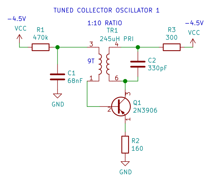
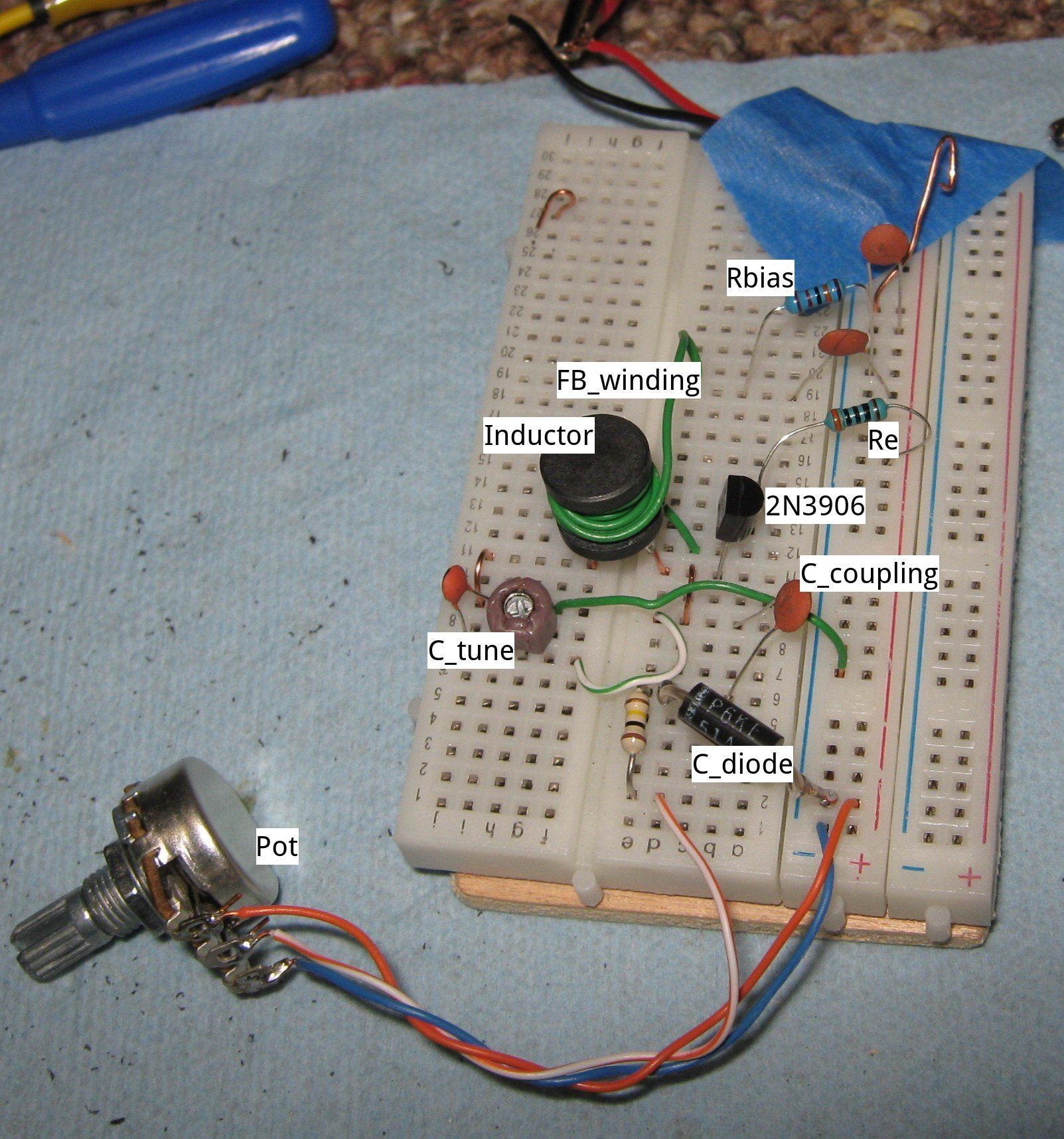
This circuit was made after combining several circuits from the internet and text books. The biasing was simplified. It started oscillating as soon as the transformer phasing was connected correctly. The inductor was salvaged from a compact fluorescent lamp ballast. Most of the wire turns were removed to get the the desired inductance. The feedback coil was wrapped around the outside of the core. The design was made to use junk box parts.
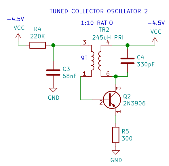
Some minor changes. Get rid of the collector resistor, increase the base bias and increase the emitter resistor. This seems to work well now. It's as simple as possible. R4 and C3 provide base bias. R5 emitter resistor stabilizes the bias. The resonant circuit is the collector load. The feedback winding is 9 turns wrapped around the inductor. The turns ratio (voltage ratio) is about 10:1. VCC is NEGATIVE 4.5V, from 3 alkaline cells. Again, the circuit is built negative so the tuning parts will be at digital negative ground. I'll just turn the page upside down before making the digital connections.
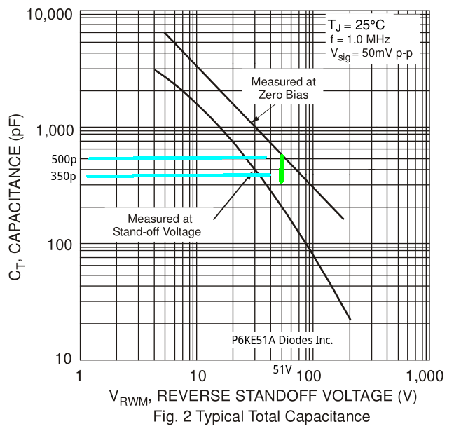
Now let's add a variable capacitance diode for voltage control tuning. I don't have real varicap diodes in my junk box. I've found TVS (transient voltage suppressor) diodes have significant capacitance. This capacitance will vary with voltage. It's maximum at 0V and goes down as voltage increases. It's very non-linear, but it is usable. I have a bag of P6KE51A samples from some old project. These should work well for VCO tuning. Hopefully the capacitance value can operate between 350 and 500 pF.
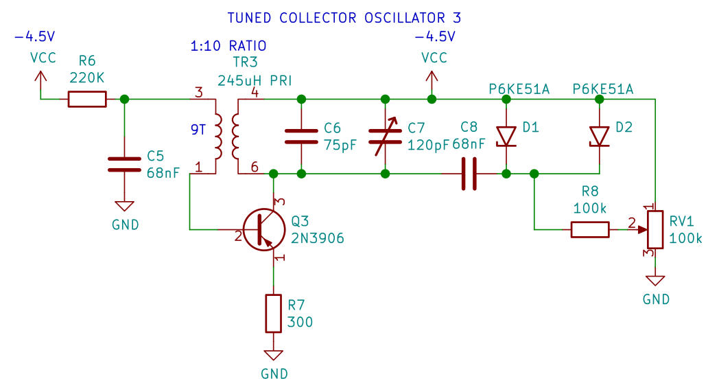
This can replace some of the resonant capacitor in the 2nd schematic. A variable voltage and a blocking capacitor are used to establish the DC tuning voltage across the TVS diode. Here's the modified circuit with the extra parts.
Did it work as designed? NO it didn't. It oscillated at a much higher frequency than expected. The TVS diodes seem to have a much smaller capacitance in circuit than was measured with a capacitance meter. Let's try 2 TVS diodes in parallel. That reduced the frequency, but the frequency adjustment range is still too small. And the waveform gets distorted at the lower frequency setting. What's going on?
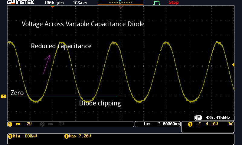
Well, there's a lot more voltage at the collector than I expected. The resonant circuit is peaking at nearly twice the VCC supply voltage. The plot above shows voltage signal directly across the tuning diode. The average voltage across the TVS tuning diode is much bigger than the control voltage. This reduces the usable junction capacitance and raises the frequency. In addition, the negative swing will bias the diode in the forward direction. This clips the bottom of the sine wave.
This idea is not going to work. It works well with fixed capacitors, but not with the variable capacitance tuning diode. Time to research a different oscillator configuration. Maybe a circuit with a resonant base circuit would minimize the voltage swing at the tuning diode.
More to follow
Discussions
Become a Hackaday.io Member
Create an account to leave a comment. Already have an account? Log In.