After searching for VCO diagrams, I found a great application note from mini-circuits.
https://www.minicircuits.com/appdoc/AN95-007.html
The explained all sorts of things about the oscillator design. The focus is on Colpitts and Clapp oscillator designs. These circuits use a pair of capacitors across the resonant circuit to generate the phase shift required for oscillation. Colpitts has been around the dawn of radio. Clapp circuit is only slightly newer. Here's what Mini-Circuits suggests for an oscillator to modify into a VCO:
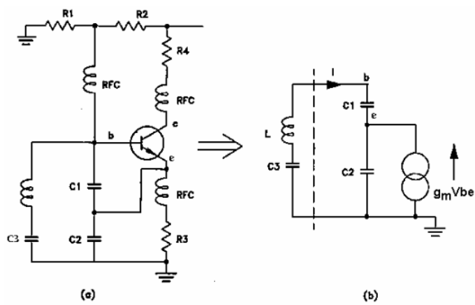
My version is similar, but has different BJT biasing, variable cap diodes added and a blocking capacitor.
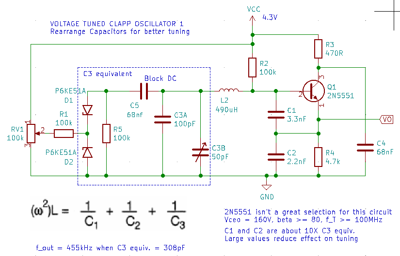
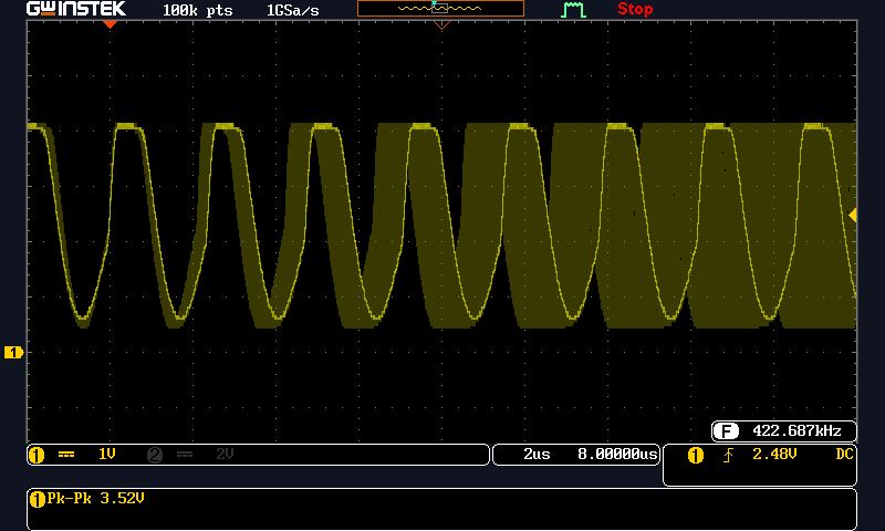
This circuit works and oscillates nicely. I think Mini-Circuits and other designs are for oscillators in the 5-20MHz range. This just isn't working well below 1MHz. After some adjustment, the frequency range was 424 to 476kHz and nothing more. That's the best it could do. The problem still comes back to too much AC voltage across the variable capacitance diodes. Here's the swept waveform:
What did I learn?
1. The DC voltage across a variable capacitance diode has to be bigger than the AC voltage from the resonant tank. If not, the AC voltage will dominate and the tuning won't work well. This limits varicap technology for low frequencies.
2. It's difficult to build a 1 transistor oscillator with limited AC voltage across the resonant circuit.
3. It's not difficult to build any of these circuits with ordinary transistors and a solderless breadboard. On the breadboard, I used every other row of contacts to minimize capacitance between nodes.
4. The capacitors in that 300 piece assortment are unstable and awful. Buy real parts to reduce frustration and confusion.
Discussions
Become a Hackaday.io Member
Create an account to leave a comment. Already have an account? Log In.