I have been using a RF signal generator from the early 1980s. It generally works, but the sweep is derived from the 60Hz AC wave at the power transformer. The sweep is unstable and the scope can't be triggered reliably. But, the 455kHz sweep does work. It uses a variable capacitance diode for sweep tuning. The sweep generator is the issue, not the RF oscillator. Same idea and same application. So how did they do it? This is partial schematic for Viz WR-50C:
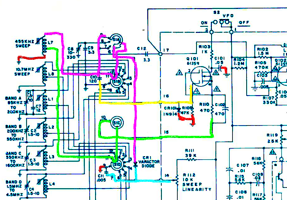
Red is ground. Violet is top of the LC circuit. Green is the inductor tap. Yellow is the signal into the MOSFET. Blue is the sweep voltage.
They are using a Hartley oscillator and a dual-gate depletion-mode MOSFET. (I doubt if that part is made any more.) The oscillator is expected to cover 85kHz to 40MHz in several bands.
So what's special about this? Nothing really, other than a very sensitive MOSFET. I'm sure they tested several versions of the design. I might use almost any MOSFET or JFET below 500kHz. The diagram above is tough to follow because of the band switch. I redrew it using the same part labels.
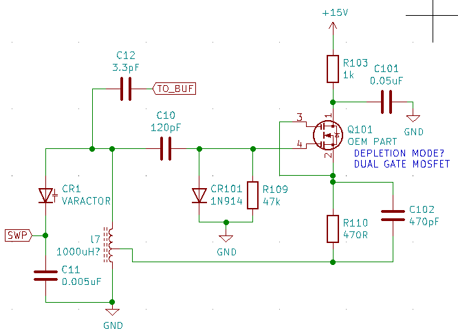
The Viz oscillator also has a diode at G1. This clamps the positive swing of the LC tank to about 700mV. Maybe that's a useful trick to limiting AC voltage across the variable capacitance diode.
To try this, I'll need:
1. Re-wind the inductor to make a tapped coil. More research is needed to figure out the tap location. Probably not critical.
2. Find a MOSFET. RF depletion MOSFETs are available on Mouser, Maybe I can use a standard N-channel signal MOSFET. I don't have any here. RF JFET would be closest to the Viz design.
3. Change DC bias for JFET or enhancement MOSFET. The voltage across R110 source resistor should equal Vgs threshold. A standard MOSFET would need positive gate bias. I can't find a data sheet for the original MOSFET.
Discussions
Become a Hackaday.io Member
Create an account to leave a comment. Already have an account? Log In.