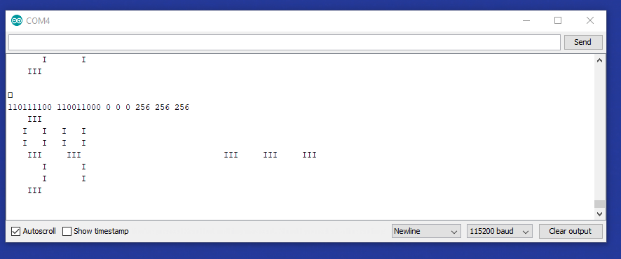
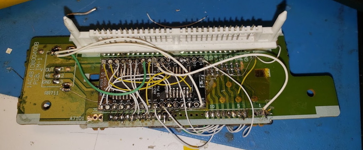
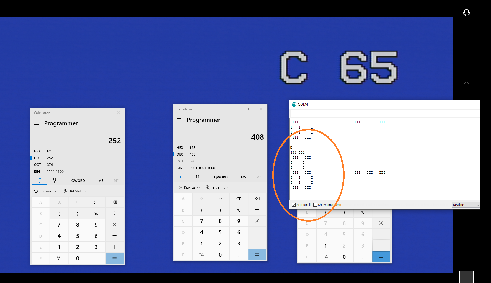
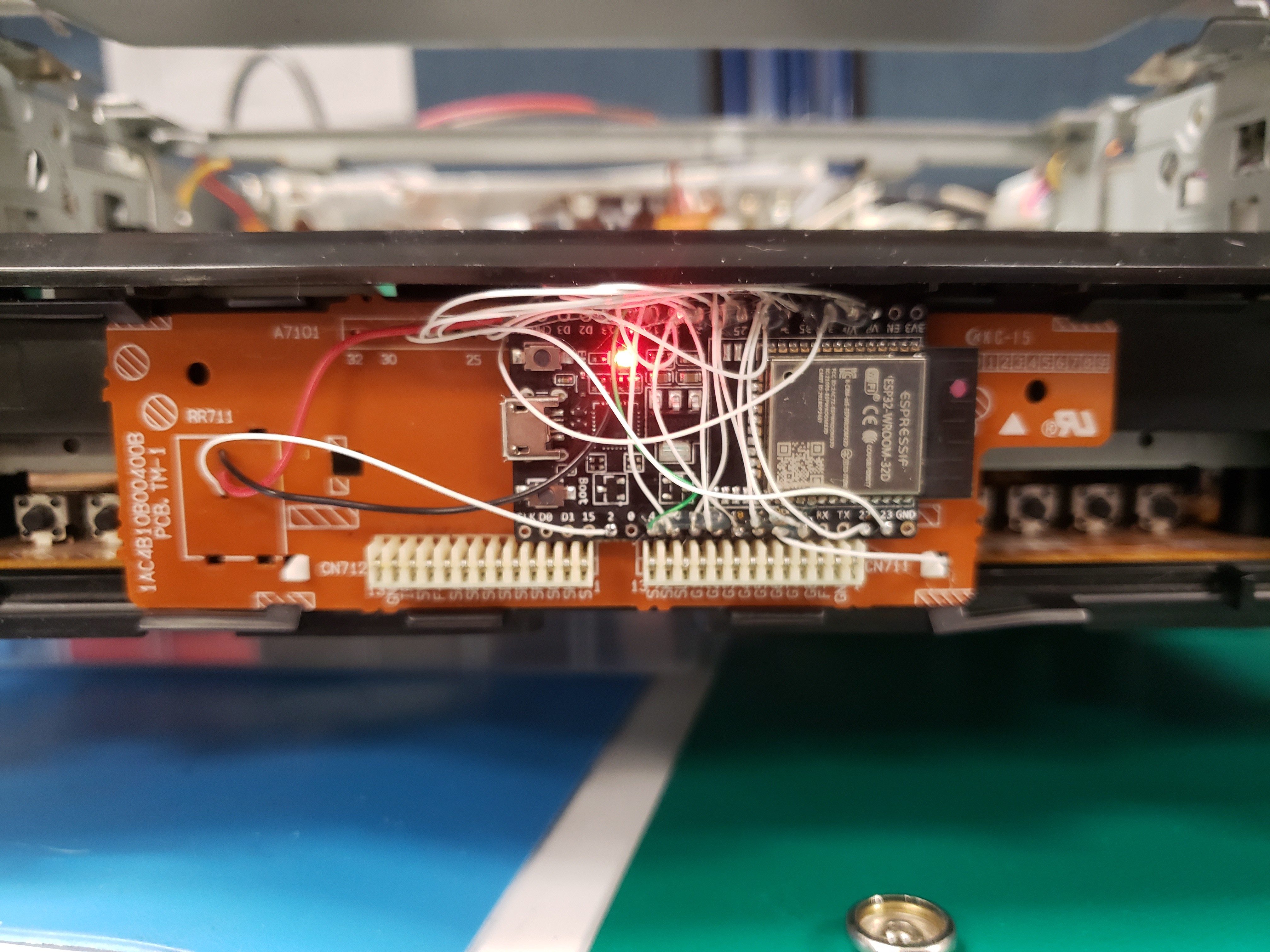
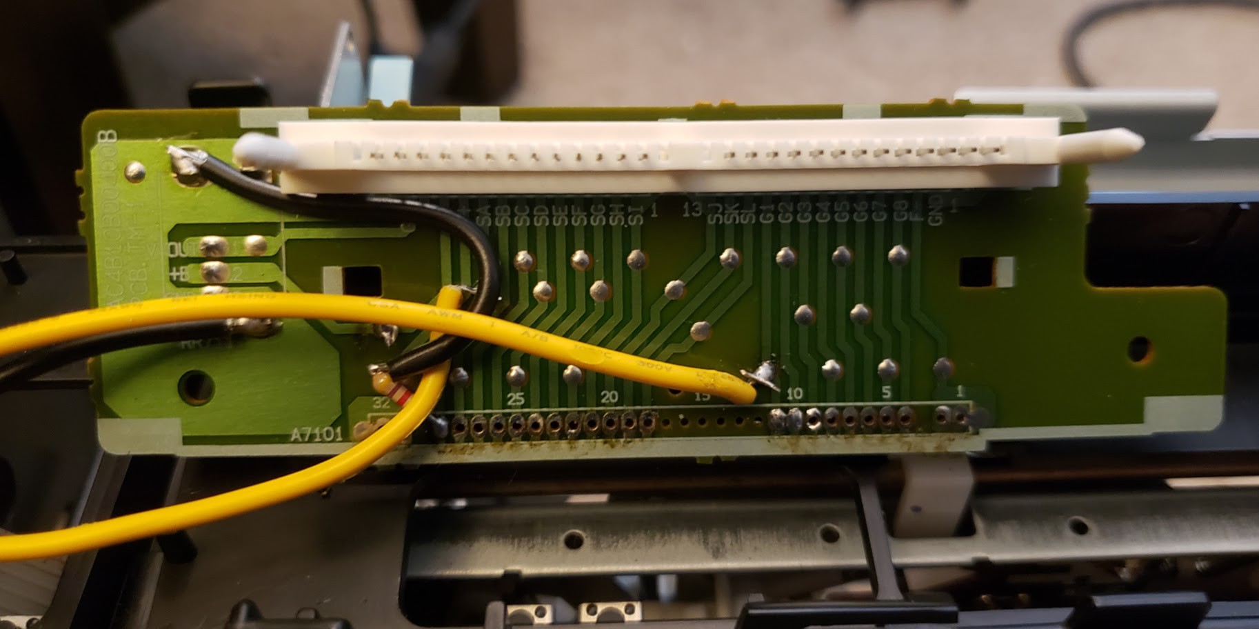
• Back on Track

    Ted04/06/2021 at 00:09 0 comments

    I decided to switch to shift registers to read in the 12 VFD segment lines to recycle some of the IO pins for future SPI peripherals. Unfortunately due to Covid, Digikey, and Mouser shipments have been heavily impacted, and receiving the 74HC166 registers I ordered took weeks. Ditto for the replacements when the first two I wired in didn't work. 

    I switched to 74HC165 registers when the replacement 74HC166 registers didn't work. The 74HC165 registers work great, and I still don't know why the 74HC166s wouldn't work. I'm happy I'm seeing expected data again, though.


  • VFD Decoded!

    Ted02/26/2021 at 11:36 0 comments

    I managed to decode some of the VFD characters. Here the VCR is tuned to channel 65, and 65 is being written in ASCII art to the serial console.


  • ESP32 Wired in

    Ted02/22/2021 at 08:35 0 comments

    I soldered in an ESP32. I powered on the VCR, and no magic smoke escaped. Next step, software!


  • Level Shifting

    Ted02/22/2021 at 05:23 0 comments

    I level shifted the 5v VFD display lines using voltage dividers. I used this method as it was the easiest to implement in the current circuit. On the Oscilloscope the line I tapped is reading 3.6v. A little too close to voltage logic high of the ESP32, but I'm not changing it now. I used 1K resistors inline, with 2k pulldowns.


  • IR Sensor

    Ted02/21/2021 at 23:48 0 comments

    IR Sensor used was Sanyo GP1U7 module.

  • Nice lil Square waves

    Ted02/21/2021 at 23:28 0 comments

    I was able to get the service manual PDF to the VHR-9413A from a nice chap in the Netherlands. I also found the JAPANESE datasheet of the LC86P6648 which I've concluded is very similar to the LC866636. The differences I've concluded are with memory configurations. With the service manual I felt confident to remove -23v from pin 48, with is the "VP" input. VP is listed as the VFD's negative power rail voltage. 

    I connected VP to GND. I pulled  SA and G1 to GND, and was able to get nice 5v sine waves of these signals.

    There are 20 lines in total. To get them to 3.3v, I'm going to cut all 20 signals, add inline resistors, and pull them down after to create voltage dividers.