 Manuel Alfonso
Battery Charger
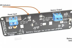
Battery charging is managed by a bq24075 IC from Texas Instruments, with the following features:
- Maximum charge current configurable through a DIP switch: 1A, 500mA, 100mA
- Reverse current, Short-circuit and thermal protection.
- Dynamic Power Path Management (DPPM): Output is active whenever a source is connected to USB or BAT, guaranteeing power to your project even if the battery has died. The input current from USB is shared and balanced between charging the battery and powering the system load at OUT.
- Battery Supplement Mode: During the charge process, when the output current exceeds the limit configured by DIP switch (1A, 500mA or 100mA), the battery supplements the system load without any regulation, so you can always get the max current provided by your battery.
You can disable the system with the toggle switch. When off, battery will be disconnected to system output and all charge will be disabled. When ON, two leds indicates a valid input charge detection (ON) and the battery charging process (CHG).
Maximum charge current can be selected through the DIP switch, with the following configurations.
| PIN 1 | PIN 2 | Max. Current |
| Down | Down | Standby (USB suspend mode) |
| Up | Down | 1A. |
| Down | Up | 500 mA. USB500 mode |
| Up | Up | 100 mA. USB100 mode |
The battery is charged in three phases:
- Conditioning pre-charge, charging at 100mA until battery raises 3V.
- Constant current fast charge, with charge current configured via DIP Switch until battery reaches 4.2V
- Constant Voltage Tapering, holding a constant voltage while current tapers off as the battery approaches full charge.
The bq24075 contain a thermal regulation loop that monitors the die temperature. If the temperature exceeds 125ºC, the device automatically reduces the charging current to prevent the die temperature from increasing further.
Also provides thermal shutdown protection, so if temperature increases to 155ºC the charge process is fully disabled, but battery will remain active to powers the load.
NOTE: Keep in mind that this features monitors the die temperature of the IC due to power dissipation, battery algorithm and its LDO output. This is not synonymous with ambient temperature.
Fuel Gauge Monitor
The board features a BQ27441-G1A fuel gauge from Texas Instruments, based on Impedance Track™ Technology, that accurately predicts the battery capacity and other operational characteristics of a single Li-based rechargeable cell. The fuel gauge measures the charging and discharging of the battery by monitoring the voltage across a small-value sense resistor (10mΩ). When a cell is attached to the fuel gauge, cell impedance is computed based on cell current, cell open-circuit voltage (OCV), and cell voltage under loading conditions.
The IC is interrogated by a STM32G031G8U6 microcontroller, and all information is displayed in a 0.91" OLED Display (optional purchase). This is the information displayed on the screen:
- State Of Charge (in %, always visible)
- Temperature (in ºC, always visible)
- Average Current (C, in mA)
- Average Power (P, in mW)
- Remaining Capacity (R.C., in mA)
- Battery Voltage (V, in mV)
- Design Capacity (D.C., in mA)
- Full-Charge Capacity (F.C., in mA)
- State Of Health (HLTH, in %)
You can cycle through this information by pressing the switch button.
Once battery inserted, the information displayed is based on the IC algorithm with the default register data. As we make charge and discharge iterations, these registers will be adjusted to show more accurate values, but keep in mind that this information will be reset to default values once battery is removed.
For a proper operation, some of these registers must be configured based on the specs of your battery: Design Capacity (the mAh value of the battery), Design Energy, Termination Voltage (value that represents 0%) and Taper Rate. The microcontroller detects when the battery is removed and setup this values again once inserted.
You can use the provided source code (link) to easily adjusts these...
 Walid Issa
 Stefan Wagner

 x-labz