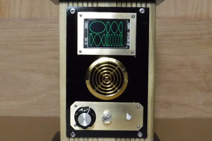
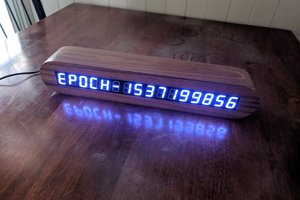
Although the display area is limited in the amount of data that can be shown at any one time, it lends itself ideally to the display of bit data.
As such there is sufficient area to display 4 x 4 bit binary words to represent time with notifications and selection modes.
The display is split into 3 main areas; Time, Selection and Modes.
Time
Sixteen LED's assigned to Time, each column of 4 LED's is assigned to a time interval, the intervals being in the form H, H, M & M.
Each bit of the Binary word has a weighting of 1, 2, 4 & 8 with the LSB on row 4 and the MSB on row 1
Each Binary 4 bit word allows a count of 0 to 15, which is more than sufficient for the 24H time format, requiring a maximum count per column of 2, 9, 5 & 9.
Selection
One row of 4 LED's at row 0 are used to identify the time column selected when entering time.
Modes
One column of 5 LED's at column 4 are used to identify Modes, Functions and Operation.
Tick - LED 4,0 flashing on & off is used to indicate Seconds and operation.
Time - LED 4,1 indicates Time mode when on. (Default mode at switch on)
Alarm - LED 4,2 indicated Alarm mode when on.
Alarm Notification - LED 4,3 & LED 4,4 flash when the Alarm is triggered.
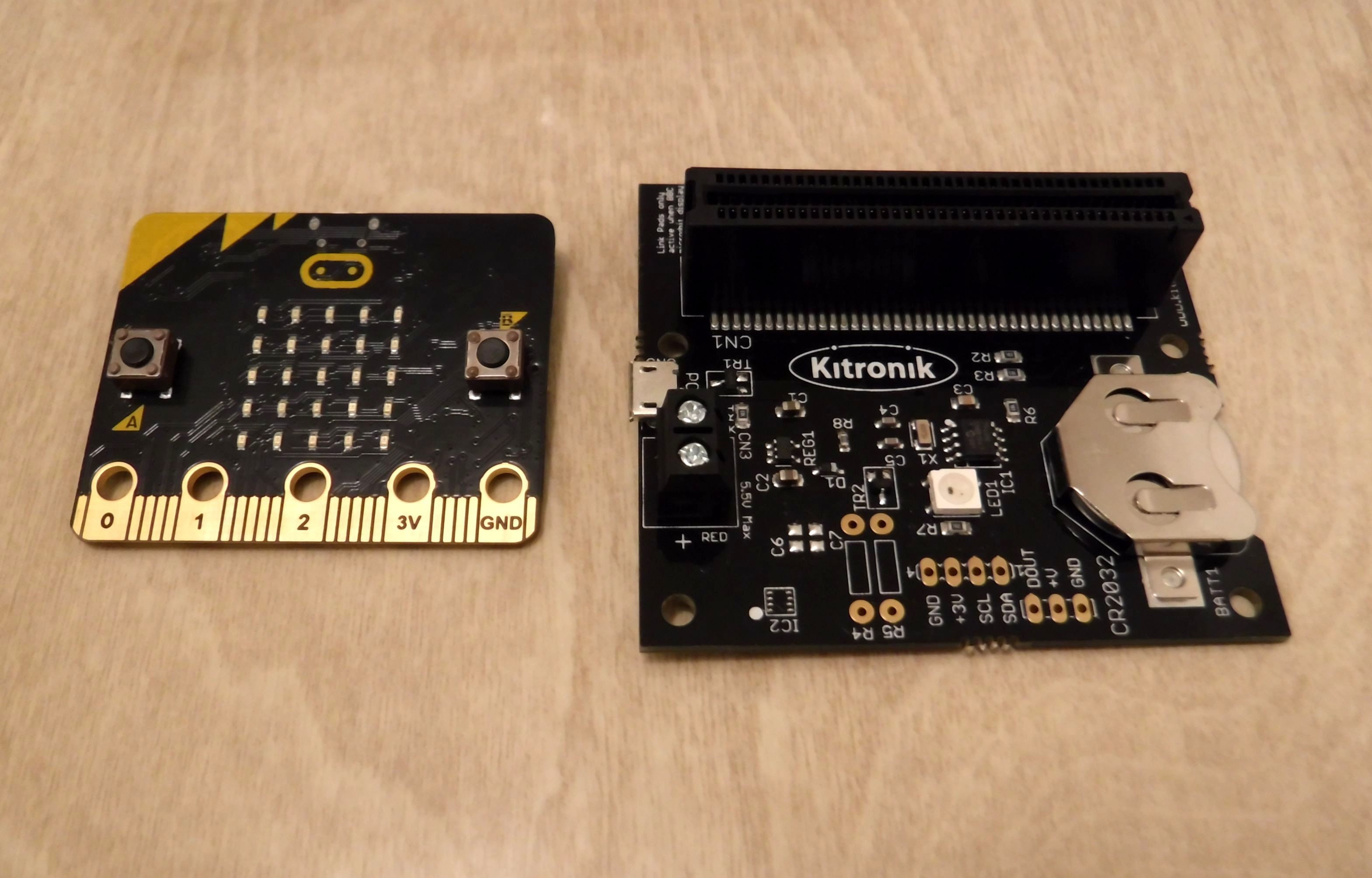
The RTC is the beating heart of the application, allowing the setting & keeping of accurate time.
Further details of the RTC can be found at Kitronik.
The RTC provides a regulated supply negating the need to power the Microbit by its own USB or JST connector and battery backup is provided to retain the time in the event of power loss.
Before using the RTC you will need to load the Extension package.
Using Makecode from the Settings icon, select Extensions and type Kitronik RTC in the search.
Select the package to install it and it will be added to the other extensions.
There are a number of code blocks to read from and write to the RTC.
We will only require 4 of these code blocks for the Binary Clock.
These will be utilised to write the set time to the RTC and to read the time back to update the clock display.
The first part of the code is program initialisation of variables, arrays and informative text.
Init
Bclk – Binary Clock
<Sel - A button selects the column that will be adjusted for time setting.
>Inc – B button increments the time.
Pressing both A & B buttons together changes the mode between Time & Alarm.
Strval – is the string value containing the time in the form “HH:MM:SS” returned from the RTC
Only HH & MM are used to display or set the time.
Mode – retains the mode value for Time = 1 and Alarm = 2 selected with the A+B button combination.
Period – is the value for the time column, selected with the A button.
0 = column 0 (H), 1 = column 1 (H), 2 = column 2 (M), 3 = column 3 (M)
Tick_en – Enables = 1 or Disables = 0 the tick (seconds), indicator.
Inc – Intermediate storage of the incremental time setting value.
Tm_list[] – stores the value of each time column during setting.
Alarm – Enables or Disables the Alarm indicator.
The forever continually calls the tick function.
Tick
The tick function which is normally enabled, displays an alternating on/off LED in the top right hand corner to indicate operation and seconds.
Additionally, it calls the showtm function which reads the RTC and processes this to be displayed in binary, whilst also calling alarm_mode, if this is enabled displays the alarm notification LED’s in the bottom right hand corner.
Showtm
Function showtm, calls rdtime and the value used from this is strval containing the time string.
A loop is created which increments through strval extracting each single number and ignoring the separator “:”
Each single number is then converted into its binary equivalent with function dec2bin and assigned to the correct column.
Rdtime
Function rdtime, reads the first 5 characters in the string returned from the RTC (ignoring the seconds portion), and passes it to strval....
Read more »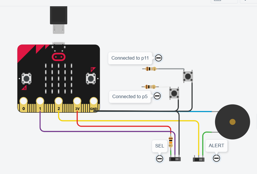


 clewsy