Close
0%
0%

RemuterMCS

Remote control for muting and unmuting the microphone, camera, and speakers

Public Chat
Similar projects worth following
Oh, sorry. I was on mute.

Like everybody else, I spend a lot of time on computer conference calls these days. I wanted to have a way to quickly mute or unmute my microphone without having to think too much, without having to find the video conference application behind whatever window I was doing "research" in, and so on.

That's not a very unique need. It's not just because I'm a tinkerer that I haven't found something that suits me. This project describes how I made something that I like. Maybe after I describe it, you'll think it's what you need, too.

In case you are wondering, "MCS" stands for Martian Chronographic Spectrometer. Or something.

I usually wear a bluetooth headset when I'm on a conference call. Like all courteous people around the world, I mute my microphone when I'm not talking. If I have to do anything outrageous, I also turn off my camera. There are times when I get out of my chair and move around, to get a cup of coffee, to deal with the family cat, or whatever. But if I have to say something on the call, I don't want to have to dash back to my keyboard to unmute myself.

So, that leads to these requirements:

  1. I don't want the control to be tethered via a USB cable or any other kind of wire.
  2. I want the control to be compact enough that I can carry it in my hand while also holding a coffee cup and maybe an unhealthy snack item and maybe some kind of cat shenanigans.
  3. While juggling all that stuff, I want it to be resistant to accidental key presses so I don't unmute myself unintentionally.
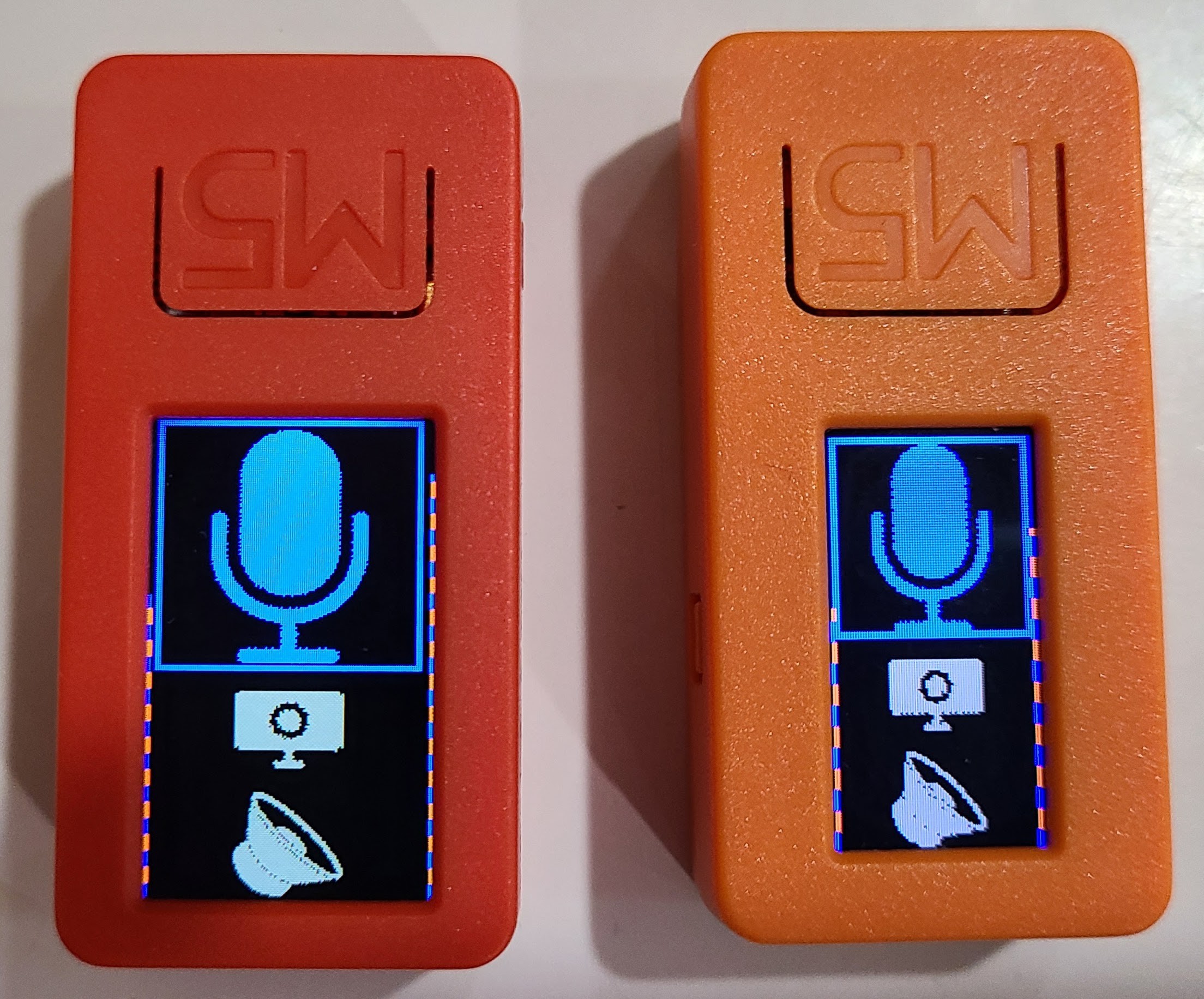
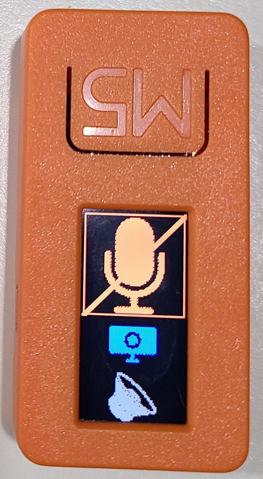
  4. I want to be able to tell, without exerting too much brain power, whether I am currently muted or unmuted.
  5. My primary concern is muting and unmuting my microphone input, but if I can get it, I would like to be able to turn my camera off (and back on, I guess, but that's mostly for symmetry), and I wouldn't mind being able to mute the speakers (even though, as I said, I'm usually on a headset).

I've thought about this project enough that I'm pretty sure what I'm going to use, but it keeps oscillating back and forth between pretty hard and pretty easy. I'll describe my research of alternatives and the actual development in the project log. If you read the project log, I suggest you start with the earliest entry and read them chronologically.

Here is a brief overview video that I made pretty well into the project. I put a link to it here so you can see where things get to after a bunch of time passed.

  • Gained by counting sheep

    WJCarpenter1 天前 0 comments

    The more I think about this, the more I think I didn't fully pursue the various low energy sleep states of the ESP32. It's been a couple of years, but I think my thinking was that after a wake-up I'd need to go through the BT connection process again.  That would just take too long. In re-reading some of the BLE material, I think I now understand that things can be relatively immediate after the one-time pairing/connection is taken care of. It doesn't help that BT and BLE throw up a jargon barrier. I was kind of tuned into that a few years ago, but it's faded now. I'm not completely sure of my facts on pairing versus connection for BLE, but I'll try to figure that out experimentally.

    The best power-savings is had by putting the ESP32 into deep sleep mode. On wake-up, the ESP32 goes through the entire boot-up sequence. My previous code was a typical Arudino-esque sketch with setup() and loop() functions, and the assumption that setup() would only run once. If I go with a deep sleep, I'll be running that setup() function over and over, so I'll have to rejigger things so that that makes sense. I'll want to turn off the BT radio during sleep and make sure it's turned back on at wake-up, but I also don't want to go through the whole connection process each time.

    The ESP32 has a built-in RTC with some killobits of static RAM that can be used for state storage during sleep. That doesn't survive a real reboot, so I will still have to use "preferences" memory for a few things. (The M5StickC has a separate RTC. I'm not sure why, but maybe it will become apparent as I experiment with things.) GPIO pins associated with the ESP32 RTC can be used to cause a wake-up. 

    Those RTC pins suggested to me reworking the UX by putting meaningful buttons on some of those GPIOs instead of completely relying on the built-in buttons of the M5StickC. Those built-in buttons were OK for me, but they're not completely intuitive for someone else, and the little buttons are slightly annoying to press. I'm now thinking of embedding the M5StickC into a 3D printed case. A few of the lines from the 8-pin connector, which luckily are RTC GPIOs, will lead to physical buttons for control of microphone, camera, and speaker. The big button on the face of the M5StickC can still be used for something; I'm thinking it will just be for turning on/off the display, with all the action on the new trio of buttons. With the new case, I might also have a separate LiPo battery if I can get away without too much circuit complexity (since I'm thinking of putting it all on a mini-breadboard).

    Pins available on the M5StickC:

    GPIOWhereRTC?
    268-pinyes
    36 or 258-pinyes (both)
    08-pinyes
    32groveyes
    33groveyes
    37button (A)
    39button (B)yes
    35button (power)yes

  • Tik Key

    WJCarpenter5 天前 0 comments

    I happened to come across this bluetooth gadget recently. It's the Mars Fox BT Multimedia Music Player Remote Control. The packaging instead calls it a Tik Key Wireless Remote.

    It looks promising enough and was cheap enough that I went ahead and bought one. It's about 30mm wide, 80mm long, and about 9mm thick. It fits very nicely in the hand. It's also got keys with graphics that could plausibly suggest to someone camera, speakers, and microphone (the phone icon). It runs on a coin cell battery. I don't know how long it would last, but there is an on/off slide switch on the side.

    You have probably guessed that I promptly took the thing apart. The front cover is not snapped on with little tabs. Instead, it was just held in place with some kind of sticky glue, and luckily it still held when I eventually put it back together. The point of opening it up was to see what I could find out about it. The couple of chips on the board were painted so that I couldn't find any markings. The most promising marking on the PCB itself was "LEASUN BR906", which was enough to get me to the FCC details at https://fccid.io/2ADQKBR906. The internal photos looks just like the device I held in my hand. The external photos and the user manual showed different icons on the keys. I assume this is just a variation of firmware for some other use case the manufacturer had in mind.

    I set about trying to find out what keyboard keys would be sent for the buttons. I tried a hatfull of different tools for that, but the most useful was the Linux utility "showkey". It can reveal both keycodes and scancodes. "showkey" works best on a virtual terminal session. Otherwise, the keypresses also sometimes do things in the Linux GUI.

    I'll probably come back later and edit in a little table of the keycodes and scancodes for those buttons. For now, I'll just mention a couple of peculiarities that I noticed.

    • The button with the camera icon is intended to trigger the camera shutter on a mobile phone. It sends the same scan codes as the "+" on the directional pad. I guess the mobile phone was be context sensitive to that combination so that it does the right thing, depending on what's on the screen.
    • Although it sends the same scan codes (one set for press and one set for release), the camera icon button only sends the press even though you've already released the button. The release is still queued and gets sent ahead of whatever button you press next. I assume this is a little bug in the firmware. The audio mute button doesn't have this problem. On my Android phone, that quirk doesn't show up for the user, and things behave as expected. On my Linux box, the pop-up for muted speaker keep chittering at me until I press some other button; I believe it thinks I am holding down the mute button.

  • The augmented box

    WJCarpenter5 天前 0 comments

    In on of the early project logs, I mentioned remote controls that are really miniature wireless keyboards. Some use bluetooth, and some use a tiny USB dongle for a mostly undocumented over-the-air protocol. (I suspect that the manufacturers source the dongle part of it and some libraries from a small number of common sources, so it might actually be possible to track down the protocol details. That's a bit technically interesting, but probably not relevant for this project.)

    One of the ideas I've been pondering is re-housing one of those in a custom enclosure with my own special purpose buttons. In other words, disassemble the remote and take just the circuit board and battery stuff and put it into a custom enclosure. Assuming the PCB has accessible make/break pads for the keypresses, I can solder wire leads to selected keypad positions on the PCB.

    The enclosure would also have buttons for enabling/disabling microphone, camera, and speakers. I would have to be extremely lucky to find an off-the-shelf remote that worked close enough to the way I wanted it to so that I could just wire the buttons directly to the PCB keypads. A different kind of luck would have me finding a remote that I could flash with custom firmware. I don't feel like I'm going to have that kind of luck, so the buttons would have to be wired to some kind of microprocessor which then simulated button presses on the remote.

    • As I've already bemoaned, these kinds of controls typically work as toggles. Without visual feedback, it's easy to lose track of what's turned on and what's turned off. My idea of using separate keyboard inputs for on and off would be hard to realize.
    • Many of these remotes require chording for some logical keys to be sent., and sometimes the chording has constraints on the timing and sequence for the chording; for example, press "shift" and then press a letter key.

    Assuming a mircroprocessor in the middle, between the custom buttons and the remote keypad, I probably need 15 or so GPIO pins to implement the logic without being overly clever.

    So we'd have a custom 3D-printed enclosure with a stripped down remote control PCB, a microprocessor, maybe a battery pack for the microprocessor, half a dozen momentary pushbuttons, maybe a few LEDs for feedback, and a rat's nest of wires holding things together. If I got far enough and still had the energy, I could eliminate most of the rat's nest by producing a custom PCB., which is pretty easy these days.

  • Things change

    WJCarpenter5 天前 0 comments

    I had put this project aside for a few years. That was mostly because my experiments with the M5StickC showed fairly disappointing battery life in the absence of sleep states. Using sleep states requires some cleverness to keep the BT connection alive enough that response time stays snappy. I was planning to try to figure all of that out, and then ... well, I didn't.

    Meanwhile, my circumstances have changed. My participation in video conferences has dropped way off. It's so infrequent now that I no longer have the use case that inspired the need for this gadget. My calls tend to be 1-on-1, so wandering away to get a cup of coffee or do a little Tik Tok dance routine just doesn't happen. On the other hand, someone else in my household does video conferences pretty much every day. They have the benefit of always using the same conferencing software, always on MS Windows, and rarely stepping away from the PC. 

    That has led me back to thinking about this problem, but I can now consider variations on more traditional stream decks or remote controls. I probably will not come back to the M5StickC, though you never know. It would still be an OK interface object if it were tethered via a USB cable so power wasn't a worry. But if no off-the-shelf hardware solves the problem, I might approach it with a custom microprocessor solution that has some handier physical buttons to avoid the navigational friction of the M5StickC.

    We shall see.

  • Controlling speakers with AHK SoundGet, SoundSet

    WJCarpenter04/16/2021 at 23:35 0 comments

    AutoHotKey includes some built-in commands for controlling audio devices on a PC. Although there are several device and control types, I could only get it to work with "master" speakers. There's a lot I don't understand about how Windows thinks about audio devices, but using "master" for the speakers is OK with me.

    • Most applications provide no control for audio output, and most also don't even provide any UI feedback on the state of audio output. They seem to feel like it's Somebody Else's Problem.
    • I use a variety of different "speakers" from time to time (multiple headphones, built-in laptop speakers, HDMI audio to my monitor). I'm skeptical about being able to control the right device at the right time. (In fact, even as a PC user operating the controls with my mouse, I find things get kind of bonkers sometimes.)
    • The "master" control provides visual feedback in the little speaker icon in the system tray.

    The AHK SoundSet command will let you explicitly turn speakers on or off, and it also will let you toggle things. Even though I have disparaged hotkey toggles, I found it convenient to use it for implementing speaker control in this AHK function. SoundGet returns either "On" or "Off" for the state of muting of the speakers. To unmute the speakers, we want to "turn off the mute function".

    ; Control-Shift-F11 mute speakers
    ^+F11::
      SpeakerControl("On")
    return
    ;;;;;;;;;;;;;;;;;;;
    ; Control-Shift-F12 unmute speakers
    ^+F12::
      SpeakerControl("Off")
    return
    
    SpeakerControl(StateWanted)
    {
      ; mute state "On" means the speakers are muted
      ; mute state "Off" means the speakers are not muted
      SoundGet, MUTE_STATE ,,MUTE
      if (StateWanted != MUTE_STATE)
      {
        ; this toggles mute state, so we only do it if appropriate
        SoundSet, +1, ,MUTE
      }
    }

  • These keys are so hot

    WJCarpenter04/16/2021 at 23:05 0 comments

    I originally thought that the computer side of this was going to be the easy part. And, I guess it is or it isn't, depending on how you look at it.

    If you are only interested in using a single video conferencing application, and if you can live with the ambiguity of keyboard shortcuts that act as toggles, then you can customize the RemuterMCS keyboard codes on the remote device to do your bidding. For example, here are the keyboard shortcuts I found for some popular video conferencing applications:

    ; Google Meet default Windows shortcuts
    ; https://support.google.com/a/users/answer/9896256
    ; microphone toggle: Control-d
    ; camera toggle:     Control-e
    
    ; Webex Meetings default Windows shortcuts
    ; https://help.webex.com/en-us/84har3/Cisco-Webex-Meetings-and-Cisco-Webex-Events-Accessibility-Features
    ; microphone toggle: Control-m
    ; camera toggle:     Control-Shift-v
    
    ; Zoom default Windows shortcuts
    ; https://support.zoom.us/hc/en-us/articles/205683899-Hot-Keys-and-Keyboard-for-Zoom
    ; microphone toggle: Alt-a
    ; camera toggle:     Alt-v
    
    ; Microsoft Teams meetings and calls
    ; https://support.microsoft.com/en-us/office/keyboard-shortcuts-for-microsoft-teams-2e8e2a70-e8d8-4a19-949b-4c36dd5292d2
    ; microphone toggle: Ctrl+Shift+M
    ; camera toggle:     Ctrl+Shift+O
    

     I really don't care for the simple toggles that the standard hotkeys use, and I myself use multiple conferencing applications. So, I started looking at my original plan, which was to have AutoHotKey do the heavy lifting. 

    That's still my plan, but it takes a little detective work to figure out the details. I was hoping to have a recipe so anybody could figure out what they needed to paste into an AutoHotKey script, but it turns out that there are a lot of variables. Part of the problem, which I didn't anticipate, is that AHK's ability to find things in controls inside an application probably depends on the use of technology that isn't in common use any more. For example, looking at "all text in a window" pretty much comes up with nothing useful. I had originally planned to look for text "Mute" or "Unmute", for example, to know the state of the microphone mute.

    In the next few project logs, I'll describe some of the techniques I am using to find and change states of devices. I don't yet have a simple recipe, but maybe that will arise as I document my trail. Ironically, the least useful of the 3 devices, the speaker, is the simplest to control via AHK.

  • Brief video demo of RemuterMCS

    WJCarpenter04/11/2021 at 19:06 0 comments

    The user interface is done enough, and I finally got around to making a short demo video of the gadget in action.

    It's just the basics of operating it, so I don't go into detail about all the configuration options and so on.

  • Is this radio on?

    WJCarpenter03/29/2021 at 02:18 0 comments

    I've pretty much finished fooling around with the firmware on the M5StickC. It's been great fun clicking the buttons and seeing the AHK pop-ups on my computer screen, but I now want to work on making AHK actually do the things it says in the pop-ups.

    I got a M5StickC Plus, which has a larger display, and adapted both of the screen renderings to the larger size. The code now runs fine on either kind of device, but you do have to say which it is in a RemoterMCSconfig.h before building and uploading the firmware. They use different TFT video controller chips. I don't think it's technically possible to have one firmware that serves both devices. If I ever figure out a way to do that, I can eliminate the configuration step.

    Here is a photo comparing the two devices, M5StickC Plus on the left, M5StickC on the right. (I don't know if they are intentionally different shades of orange or if it's just variation from different manufacturing runs.) For both displays, the dashed vertical bar on the right side is the battery indicator. The stripe on the left side is Received Signal Strength Indicator (RSSI) of the connected computer. The RSSI varies quite a bit, but it does give a coarse indication of strong or weak signal. (I don't understand why, but it seems a Bluetooth server, which is what these are, must ask the Bluetooth client for its RSSI value. Since both ends are receiving signals, I expected to be able to ask my radio what RSSI it had seen. But, apparently not.)

    One thing I have to come back to and hope to improve is battery life. There's a lot I don't know about Bluetooth LE, even though I know a lot more today than I did when I started this project. I want to figure out how to put the ESP32 into light or deep sleep most of the time to save power. I know how to do that, but it kills my Bluetooth conversation with the computer. This could be something that needs a code change in the ESP32-BLE-Keyboard library, or it may be something I can overcome with other BLE or ESP32 calls in conjunction with that library. I have to study that some more.

    My simple battery longevity testing was disappointing, but fairly conclusive. Regardless of how much delay() I put into each iteration of the Arduino loop(), the lifetime of the M5StickC battery is between 40 and 50 minutes. It's not too surprising that the amount of delay() doesn't matter too much since the processor continues to run at full speed. On the ESP32, delay() just makes an RTOS call to suspend the foreground task for that amount of time. The clock keeps ticking.

    I repeated the longevity timing with a modified program that didn't do anything with the Bluetooth radio. It wasn't even initialized. I got between 110 and 120 minutes that way. More than double, less than triple. It gives me some encouragement that if I can crack the light/deep sleep puzzle so I can continue BLE when I wake up, I should be able to get a lot of battery mileage. When starting from scratch, it can take from 1-10 seconds to establish the Bluetooth connection, which is pretty unacceptable for this use case. 

    I just need to figure out how the Bluetooth remote control folks do it. I'm sure their devices sleep most of the time. I paged through the BLE documentation intended to facilitate the low power part, but there's a lot of jargon and a lot of layers of APIs, so it's taking me a while to match things up. I haven't yet come across a good example, although there are plenty of examples that don't worry about power. 

    EDIT: I figured out how the remote control people do it. They use more special purpose Bluetooth chips that are optimized for it. The ESP32 will probably never be able to be that efficient, but it should be able to do a lot better than it does for me right now.

  • Battery percentage, note 3

    WJCarpenter03/26/2021 at 04:01 0 comments

    I suppose it's due to the relatively small battery, but things seem to go pretty unevenly as it charges and discharges. I am still using a strictly linear approximation for how much battery remains, but I'm a little skeptical that it's correct or any more than grossly meaningful. I draw a bar along one of the long edges of the display to show the remaining battery.

    I verified by checking registers in the AXP192 that the automatic shutdown voltage is 3.0v, as documented for the M5StickC. FWIW, the L1 and L2 warning levels are 3.45v and 3.40v, respectively, but they are not used for anything by default.

    With my previously described technique of recording the high and low voltages observed, the lowest I ever saw was a little above 3.4v. I suspected it was the granularity of the 10 minute intervals that was givng me that puzzling value, so I changed the timing to observe and record the low voltage every 40 seconds, and that showed me a low voltage of 3.0778v. That pretty much confirms that the AXP192 is behaving as expected and shutting things down at 3.0v.

  • Bright breath

    WJCarpenter03/26/2021 at 03:53 0 comments

    For the M5StickC, the brightness of the TFT display is not controlled the way you might expect, with a PWM operation on a GPIO pin from the ESP32 processor. Instead, the backlight is wired to an output pin of the AXP192 power controller. The voltage supplied by that pin can be programmed to provide 1.8v to 3.3v in 0.1v increments.

    M5's Arduino IDE library for the M5StickC provides an AXP192 method called ScreenBreath(). I don't know why it's called that, but what is does is set a value to control the output voltage from that pin on the AXP192. That saves you a small amount of trouble in doing it yourself over the I2C interface. Interestingly, even though the AXP192 would accept values 0 - 15, the M5 API limits the upper range to 12. (I suspect that's based on how much voltage the TFT backlight LED would tolerate. The M5StickC product page says "2.8v max200ma". The AXP192 default output voltage is 2.8v. Maybe not worth sacrificing a device to find out what happens when you overdrive the backlight LED. :-) )

    I did some experiments, and the display is completely dark with any value of 7 or below (at least for my eyes with the M5StickC that I'm testing).

    So, realistically, the usable values are 8, 9, 10, 11, 12. 

    I provide a configuration item for setting the display brightness in my sketch. I don't limit it at either end, but the above limits are still there.

View all 22 project logs

Enjoy this project?

Share

Discussions

Similar Projects

Does this project spark your interest?

Become a member to follow this project and never miss any updates