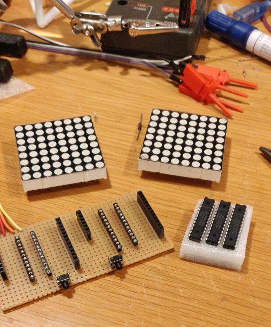
• Hardware - not simulation

    Michael Möller03/31/2021 at 21:20 0 comments

    The hardware version will be "slightly delayed", as in probably never done. My soldering skills on a perfboard are not that great, and I have misinterpreted the pinout of the chip.

    Initializing the SPI

    In the simulation it was sufficient to

    ; Set MOSI and SCK output, all others input
    ldi r17,(1<<DD_MOSI)|(1<<DD_SCK)
    out DDR_SPI,r17
    ; Enable SPI, Master, set clock rate fck/4
    ldi r17,(1<<SPE)|(1<<MSTR)
    out SPCR,r17
    

     which is more or less what the ATmega datasheets gives as example. 

    In RealLife® it is not that simple. I discovered that the Arduino itself would hang every now and then when putting data on the SPI (and that took a long to debug - never seen it do that before). It did so whether something was connected or not. If I used the library

    SPI.begin()

    it would not hang. (I had other issues with my circuit, so not everything worked, but a) the Arduino did not hang and b) the few LEDs I did control where behaving as expected) It did not matter whether I used a pure C that did direct port access to initialize or assembly.

    I got the assembly listing from the generated C code with SPI.begin(), and the proper way to setup the SPI seems to be

       ; set pin 10 high,to avoid an initial pulse
       in   Tmp,PORTB
       ori  Tmp,0B00000100  ; pin 10
       out  PORTB,Tmp
       ; now set it output
       in   Tmp,DDRB
       ori  Tmp,0B00000100  ; pin 10
       out  DDRB,Tmp
       ; Set the SPI controls (needs to be two seperate setting of one bit each?!)
       in   Tmp,SPCR
       ori  Tmp,0b01000000   ; "SPCR |= (1<<SPE);"
       out  SPCR,Tmp
       in   Tmp,SPCR
       ori  Tmp,0b00010000   ; "SPCR |= (1<<MSTR);"
       out  SPCR,Tmp
       ; Now set the 11 and 13 as output
       in   Tmp,DDRB
       ori  Tmp,0b00101000
       out  DDRB,Tmp
    

    That initializes the SPI port without problems ("Tmp" is a synonym for r16)

    Afterwards, one has to send SPI commands to the chips to initialize them, this is kindly pointed out in the notes for the project: following sequence of commands: 0f 00 0b 07 0c 01

    The first byte is the "row number" of the matrix, but that only goes to 8, so 9-F addresses an internal register in the chip that configures it. In my case this meant the initialization, after the SPI was initialized, continues with

       ; Initialize the chip(s) from their startup state
       cbi   PORTB,CSS       ; Trigger a "new transaction" on MAX7219 (pin 10 LOW)
       ldi   Tmp2,0x0C       ; powersave register:
       mov   Tmp3,One        ;   1 = Power UP
       rcall SendTwo
       ldi   Tmp2,0x0F       ; testmode register
       clr   Tmp3            ;   0 = normal operation
       rcall SendTwo
       ldi   Tmp2,0x09       ; decode mode register
       rcall SendTwo         ;   0 = binary passthrough
       ldi   Tmp2,0x0B       ; scan mode register
       ldi   Tmp3,0x07       ;   up to 7th, ie all 8 digits(=rows)
       rcall SendTwo
       ldi   Tmp2,0x0B       ; intensity register
       ldi   Tmp3,0x07       ;   4 = quarter intensity
       rcall SendTwo
    

    The SendTwo routine just sends the bytes from Tmp2 and Tmp3 on the SPI and waits for completion. Oh, and this only for one chip, I was going to implement a "SendFour" which would duplicate the bytes so both chip (the SPI is daisychained) get the same commands.

    The Real Hardware

    I screwed up here, a little to eager, and mixed up a few pinouts. The board worked for a while, with only a few matrix row/columns connected, (with the Pong code!) so I know the initialization works, but when fully populating it something happened and I probably will buy a readymade board rather than new Max7219 chips (the throughhole versions are not cheap)

    Over-and-Out

  • Pong in ASM (barely pass)

    Michael Möller03/30/2021 at 11:07 0 comments

    OK, so the software/simulator version is done. I'll probably get a C or D for this version.

    https://wokwi.com/arduino/projects/290809734244598280

    Done: The ball bounces, the bats move, it stop when it hits the wall either side

    Underachievment: buttons debounced by screen framerate, ie player can only move his bat once for every ball move, and button must be depressed at the framechange (a short press will be missed)

    I need two "timers", one for debounce and for framerate. Plenty of ways to do this and still avoid using a real timer. I could use one to show I understand interrupts. 

    Sidenote: Interrupts are evil little things. They destroy the predictability of a program. A friend who worked on machines when coremagnetic memory was "hot", said: "The computer lost it's innoncence when interrupts were included". So true, so true.

    Its 30th of March, so ... likeyhood of me improving it is low. I'm going back in the mancave and see if I can complete the hardware version

  • Pong in ASM (Buttons moving players bat)

    Michael Möller03/27/2021 at 22:13 0 comments

    Deadlines. They make this nice "whoooosh" sound as they go past. I want to avoid that, so I am shifting gears a bit here. Concentrating on making the assembler/simulator version, but only the bare minimum.

    I used to earn my living as an assembler programer some - ehrm ... <cough cough > ... over 40 years ago. Compiled programs were slower, bigger, had overhead, required an Operating system, and I was coding for standalone systems, and had some realtime requirements. Anyhow, doing the AVR assembly has been a little uphill with the instruction/register set, although I am sort of getting into its mindset.

    Today I am uploading the next to last version, I am only missing detecting end game condtition. I may do another version with the NPC being close to unbeatable (It is easy to make it unbeatable now) and/or adding a counter how long the game has lasted before the player inevitably looses (due to sleep deprivation)

    This is not my proudest code - style and paragdims are inconsistent. Detecting that one button has been pushed is my most obscure code relying on the Z-flag state for many instructions. I could avoid using SRAM, but wanted to do some memory access. Subroutines which are only called once is ineffcient (though it improves modularization) - one saves all register states quite needlessly and so on.

    See the v04 file

  • Pong in ASM (plus a moving bat)

    Michael Möller03/25/2021 at 15:16 0 comments

    Deadline approaching!

    Got back on track, and the hardware has encountered some problems, so now I just panic-write the simulation version to "pass" the exam - maybe I'll get back to the hardware version before deadline.

    V03 uploaded

    Had not fun debugging a strange overwriting of the few variables I have in SRAM. Minor syntax detail, if you write
     data: .byte
     more: .byte

    "nothing" happens., i.e. the DATA and MORE occupy the same byte. You need to write
    data: .byte 0
    more: .byte 0

    Says so i the manual, but other compilers will reserve space and the inital value is optional.

  • Pong in hardware

    Michael Möller03/03/2021 at 21:56 0 comments

    I have gotten some MAX7219 chips now, I found some 8x8 LED matrixes, some buttons unsoldered from a scrap board, perfboard and I have plenty of Arduinos. Time to go RealLife with this, too!

    Today I managed to get the layout done.

    The wiring schematic is very simple - one chip pinput to neares LED Matrix pin.

    As the chip pinout is not straight 1,2,3 the ordering of segment/columns will be "slightly" random, so the software will need to map logical row/colum to real ones.


    EDIT - "typo" or what you call it when there is an obvious error in the drawing. This was/is just done in Inkscape, more of a drawing/sketch than a diagram It should of course be (I've also clarified what is the chip)

    BTW, the 8x8 matrix I have are Bi-colour (Red/Green; meaning I can show Black, Green, Yellow, Red) but that would require 4 MAX7219 and I only bought 3, so it remains Red like the simulation model.

  • Pong in ASM (Bouncing Ball)

    Michael Möller02/28/2021 at 18:32 0 comments

    Of course you have to know "all" the instructions to write assembly code (just like you need to know "all" keywords to write C), and for some of them you need to know "all" the side effects, too. What you do not know by heart you have to lookup, and being new to the AVR I spent a lot of time with ^F in the manual.

    The writing took about an hour or two, much time spent just thinking and selecting the instructions. That some registers can be set to a value, and others only can copy from another register or SRAM required a little getting used to.  Some change the status register falgs, some do not - important for branch instructions.

    Originally I had set aside a number of SRAM variables, but I have so few of them I can keep it all in registers. This led to a sidetrack om how to rename registers for convinience. Not sure I'll do that in the final version. Pros and Cons to everything.

    I did the writing in a text editor, then cut-n-pasted it to the simulator. A pass or two for minor syntax errors. (Sometimes the Assembly syntax errors may not show in the text window. Open the browser console window (Shift-Ctrl-I for the Chrome browser))

    I started it ... and it did not run (surprise! - not)

    The BREAK implementation in the simulator, which dumps all registers to the browsers console window, was suffcient to find the few foreheadslapping flaws, taking less than an hour. Although the course did show a lot on using the gdb debugger, it is another large program to learn to handle. 

    The code is a little too long to display in-line in the log, so see the uploaded file of the working version https://cdn.hackaday.io/files/1779167611958144/Pong.v02.S 

    The code is a little confusing - no consistency in register allocation (Tmp2/R20 usage), not sure if using register aliases makes it clearer. I alternate between "tense"/"smart" code and clear or obvious code (but less efficient). The symbol/defines to handle different display sizes is non-functional, 8x16 is hardwired in some parts. I could write it cleaner, but not this time.

    I have sketched out my basic flow diagram and routinesfor a minimum working game. But first another partial version, where I only have the two bats, one controlled by buttons (the player) the other by a timer (the computer).

  • Pong in ASM (Display "something")

    Michael Möller02/27/2021 at 00:10 0 comments

    After all those "getting to know the lay of the land", I am ready to write for final product. I did this a few hours after the last class. It, too, was not without a "stupid" mistake.

    Like the C code, we first put something on the 8x16 display. This runs on the simulator.

    ;;; "PONG" in AVR assembly
    
    ; V0.1 - turn on something on the LED array
    ;      - requires sending two SPI bytes (four to get to the 2nd half)
    
    #define __SFR_OFFSET 0 // makes "PORTB" etc fit the IN/OUT Port, instead of the memory equivalent
    #include <avr/io.h>    // Get the "basic" symbolic names for registers
    .global main           ; Interface to the Arduino/C startup
                           ; (therefore?) stackpointer and vector table initialized
    
    CSS = PB2               ; Arduino pin 10 (portB, pin 2) is the CSS line
    
    ;====== MAIN, START HERE ====
    main:
    
       cli                  ; we live without interrupts
      
       ; ---- Setup SPI mode
       ldi  r16,0B00101100  ; bit 2, 3 and 5 for Arduino pins 10, 11 and 13 as OUTPUT
       out  DDRB,r16        ;   the rest as INPUT
       ldi  r16,0B00000100  ; Bit 2/pin 10
       out  PORTB,r16       ;   HIGH
       ldi  r16,0B01010001  ; Bit 0 enable SPI, bit 5 to ?, bit 7 to ?
       out  SPCR,r16        ; Set these on the SPI control register
    
       ; ---- Push two bytes to SPI, bracket by LOW pin 10
       cbi  PORTB,CSS       ; Trigger a "new transaction" on MAX7219 (pin 10 LOW)
       ldi  r17,5           ; 5th row
       out  SPDR,r17        ; send the first byte - put it in SPI data register
    1: in   r18,SPSR        ; Read SPI status register 
       sbrs r18,SPIF        ; was the done bit set ?
       rjmp 1b              ; nope, keep waiting
    
       ldi  r17,0B10101010  ; LED pattern
       out  SPDR,r17        ; ditto 2nd byte
    1: in   r18,SPSR        ; Read SPI status register 
       sbrs r18,SPIF        ; was the done bit set ?
       rjmp 1b              ; nope, keep waiting
    
       sbi  PORTB,CSS       ; pin 10 HIGH again
    
    loop:
      ; ==== Loop ====
      nop
      rjmp   loop      ; We do nothing, really fast :-)
    

    I got lost in the address mode (memorymapped vs Port#) and symbolic names, as I did want to use plain numbers for everything. For a long while everything was right but nothing came up on the display. I took a hint by reading the disassembly from the working C code, and discovered I had forgotten to toggle the pin10/CSS line.

    I have this sinking feeling that debugging in assembly is going to be hard. Actually, I used to earn my living doing assembly programming between '77 and '82 (yeah, I am not that young) so I am simply rediscovering old skills. 

    Onwards to doing the bouncing ball

  • Hardware prolog (HelloWorld again)

    Michael Möller02/26/2021 at 22:54 0 comments

    I am impressed that the Arduino IDE in real life is as comprehensive as the simulator (or is it the other way round ? ;-) ) The same .ino and .S files will compile, upload and run InRealLife as they do in the simulator. The simulator has a few more tricks (the automated view of final assembly code before upload, and the debugging facilities - BREAK does something usefull, and gdb (debugger) can be hooked up)

    As my project plan is to do it in the hardware as much as possible, and at this time of writing I only have the Arduino, (parts are on order) another HelloWorld blink LED program is called for, now with an actual loop.

    My .ino file is just a comment, this is the .S file. Hit the compile and upload button on the IDE and the real life Arduino will blink.

    #define __SFR_OFFSET 0 // makes "PORTB" etc fit the IN/OUT Port, instead of the memory equivalent
    #include <avr/io.h>    // Get the "basic" symbolic names for registers
    .global main           ; Interface to the Arduino/C startup (It will setup vectortables and stack...)
    
    
    ;====== MAIN, START HERE ====
    main:
    
       ; ==== Initialization =====
    
      sbi   DDRB,5      ; Set PB5 (Arduino pin 13) as output
    
       ; ==== Loop =====
    loop:
      sbi   PORTB,5     ; Set LED ON
      ldi   r24,lo8(1000)
      ldi   r25,hi8(1000)
      call  delayMillis
      cbi   PORTB,5     ; Set LED OFF  -- doenst seem to happen?
      ldi   r24,lo8(1000)
      ldi   r25,hi8(1000)
      call  delayMillis
      rjmp  loop
      
    ;====== delay routine (milliseconds) ====
      
    ; r24/25 - number of milliseconds. (set to zero on exit)
    
    delayMillis:
      push r26
      push r27
      
    2:; 16000 cycles
      ldi r26, lo8(4000)
      ldi r27, hi8(4000)
    1:
      sbiw r26, 1  ; 2 cycles
      brne 1b      ; 2 cycles 
      sbiw r24, 1
      brne 2b
      
      pop r27
      pop r26
      ret

    The delayMillis routine was supplied by Uri in the course, shameless cut-n-paste there. But I "improved" it by preserving the r26/27 registers. This caused a bug it took me a few hours to find (blinded by my own brilliance there). The wrong code made two push operations for every millisecond, eventually wrapping the stack, overwriting things but fortunatly stopping/looping/getting lost in never-never land before it overwrote the RESET vector (which is vital for uploading a new program(?)).  The debugging process involved running this in the simulator and BREAK everywhere until I finally could slap my forhead with the required force.

    This code, too, isnt pretty or educational, a bit inconsistent in naming,defines and so on, but I now have verified I can create working assembly-only programs on my physical Arduino.

  • ASM prolog (HelloWorld)

    Michael Möller02/26/2021 at 20:19 0 comments

    Baby steps: I first wrote a small ASM in the given template, to do the hardware equivalent of HelloWorld - blink a LED (on pin 13 for the Arduino) Writing it took 5 minutes. Getting it to work took more of an hour.

    Private project on Wokwi

    This sidetracked my for a while: The way to copy a template to a private file on Wokwi ... yeah, needs an attempt or two. Also I had an issue with my browser (I think). Actually this was the first thing I did, create the empty projects for the C and ASM version respectivly, ie. with no code.

    Assembler extensions and register addresses

    Back to the LED (pin 13): That worked without any issues. No, not true, there is getting the definitions of PORTB included. (The assembler accepts some "C"syntax stuff, ie #include, and that line has to use C comments // instead of assembler ; ... mere details =:-0 ) AVR has the unusual property that most registers can be accessed by both as a memory-mapped register and via a special IO instruction (IN or OUT), but with different addresses. The "PORTB" define is for the memorymapped version, unless you include a special define or a macro to transform between the two. Room for confusion. The assembler says "out of bound value" if you're lucky when using the wrong address-type. So this version uses absolute numeric values.

    Initializing the CPU

    I experimented with this a while. Note that we run this without any C at all, so strictly speaking my program has to initialize stack and interrupt vectors. I did this, and I forgot this (ie both ways) and it made no difference. Looking at the object dump (In Wokwi type F1,a,s,s,return, view the sketch.lst file. It does NOT update with each compile!) I saw the assembler/linker sort of ignored my code and had included some other code. This (like all other items above) had been mentioned in the course, but sometimes you do not get the significance in the presentation.

    So the long and short of it: The Arduino IDE and gcc in collusion create the interrupt vector table and initialization code for the stackpointer and thus preserves the "Upload a program" functionality to the Arduino board. (Upsetting the RESET vector may brick your CPU until you use a proper programmer)

    Uri did point out that including a special routine would also automagically initialize variables (.data region) with nonzero values.

    ;;; "PONG" in AVR assembly - actually just turn LED13 ON
    
    ; V0.0.01 - just a quicky to get the tiniest assembly program running
    
    .global main
    
    .org 0            // this does the proper setup, wrt. interupt vectors
       jmp main       // without it, program lies and runs at location 0
    
    .org 0x100 
    
    main:
      ; ==== Initialization =====
      ldi R16,0x20       ; Load bit 5
      out 4,R16          ; Direction bit: "output" for PortB, bit 5
      out 5,R16          ; Set it ON
    
      ; ==== "loop" ====
    burn:  rjmp burn     ; Burn CPU, burn !
    

    This version reduntantly creates a partial vector table. It is not "correct" but works. Also it does not blink the LED, it merly turns it on, but commenting out one of the "out" instruction shows that it is my code that turns it on.

  • Pong in C (part 1)

    Michael Möller02/26/2021 at 19:40 0 comments

    Display something (with SPI library)

    V0.1 is just to do the bare minimum in C to just light a few dots on the display. That was easy and took only "a few minutes". 

    /*
    
      PONG in C
      V0.1 - just display something
      
    */
    #include <SPI.h> // H/W uses pin 13, 12, 11, pin 11 is MOSI output
    
    void setup() {
      SPI.begin ();
      pinMode(10,OUTPUT);
      //SPI.beginTransaction(SPISettings(16000000, MSBFIRST, SPI_MODE3));  // MOSI normally low.
    }
    
    void loop() {
      digitalWrite(10,LOW);
      SPI.transfer(0x05);
      SPI.transfer(0xAA);
      digitalWrite(10,HIGH);
      delay(5555) ;
      digitalWrite(10,LOW);
      SPI.transfer(0x03);
      SPI.transfer(~0xAA);
      digitalWrite(10,HIGH);
      delay(5555) ;
    }
    

    Yes, all hardcoded values. 

    Display something (with port access)

    The second pre-test version was to avoid using the SPI library.

    This required peeking in the SPI library and (sorry) cut-n-paste the initialisation code. I tried to match this with the AVR manual description of the bits in the SPI control register. If the AVR manual was the only information source I probably would not have managed, possibly simply brute force trying all combinations until it worked.

    The same with the send-one-byte routine.

    This only took "half  an hour".

    // (Cant find where they are defined, so doing it myself
    // SPI pins are hardwired to 13, 12 & 11
    #define PORT_SPI    PORTB   // The SPI port is part of Port B
    #define DDR_SPI     DDRB    // -"-"
    #define DD_MISO     DDB4    // Port number for pin 11
    #define DD_MOSI     DDB3    // (not using this - pin 12)
    #define DD_SCK      DDB5    // Port number for pin 13
    
    byte CSS = 10 ;  // the ChipSelect pin
    
    void SPIout ( byte Bits ) {
      // Output a byte to SPI - block until complete
      SPDR = Bits ;
      while(!(SPSR & (1<<SPIF)) ) ; // Wait until complete
    }
    
    void setup() {
      // to be nicer it should mask the other pins, ie not change them
      DDR_SPI = (1<<DD_MOSI)|(1<<DD_SCK); // Set MOSI and SCK output, all others input
      SPCR = (1<<SPE)|(1<<MSTR)|(1<<SPR0); // Enable SPI, Controller, set clock rate fck/16
      pinMode(10,OUTPUT); // Ready the chip select
    }
    
    void loop() {
    digitalWrite(10,LOW);
      SPIout(0x05);
      SPIout(0xAA);
      digitalWrite(10,HIGH);
      delay(5555) ;
      digitalWrite(10,LOW);
      SPIout(0x03);
      SPIout(~0xAA);
      digitalWrite(10,HIGH);
      delay(5555) ;
    }
    

    Bouncing ball

    The last extension of this test C suite was to have a single dot bounce around. 

    .. same #defines as previous version...
    byte CSS = 10 ;  // the ChipSelect pin
    
    // Variables
    byte BallXcurr, BallYcurr ; // last, current position [0,15/1,8]
    byte BallXdir, BallYdir ; // just +/- for 45 degrees motion [0,1]
    
    void SPIout ( byte Bits ) {
      // Output a byte to SPI - block until complete
      SPDR = Bits ;
      while(!(SPSR & (1<<SPIF)) ) ; // Wait until complete
    }
    
    void RowSet ( byte RowNum, unsigned int RowBits ) {
      // Fill a whole row (16 bits)
      digitalWrite(CSS,LOW);
      SPIout(RowNum) ; SPIout(RowBits&0xff) ;
      SPIout(RowNum) ; SPIout(RowBits>>8) ;
      digitalWrite(CSS,HIGH);
    }
    
    void setup() {
      pinMode(11,OUTPUT); pinMode(13,OUTPUT) ;
      // Direct manipulation: DDR_SPI = (1<<DD_MOSI)|(1<<DD_SCK); // Set MOSI and SCK output, all others input
      // (to be nicer it should mask the other pins, ie not change them)
      SPCR = (1<<SPE)|(1<<MSTR)|(1<<SPR0); // Enable SPI, Controller, set clock rate fck/16
      pinMode(10,OUTPUT); // Ready the chip select
      BallXcurr = 5 ; BallYcurr = 5 ;
    }
    
    void loop() {
      RowSet(BallYcurr,0x00) ; // extinguish current position
      if ( BallXcurr==0 ) BallXdir=1 ; if ( BallXcurr==15 ) BallXdir=0 ; // bounce if needed
      if ( BallXdir==1 ) BallXcurr++ ; else BallXcurr-- ; // advance
      if ( BallYcurr==1 ) BallYdir=1 ; if ( BallYcurr==8 ) BallYdir=0 ; // bounce if needed
      if ( BallYdir==1 ) BallYcurr++ ; else BallYcurr-- ; // advance
      RowSet(BallYcurr,1<<BallXcurr) ;
      delay(33);
    }
    

    I spent a little more time on this, partly with finding out the up/down, numbering starting at 0 or 1, and other minor details. (We all know the devil is in the details, right?)  Sorry about the the code not being effective, pretty or educational,...

    Read more »