 Michael Möller
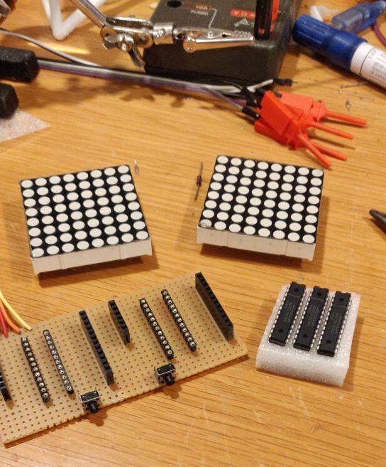
I have gotten some MAX7219 chips now, I found some 8x8 LED matrixes, some buttons unsoldered from a scrap board, perfboard and I have plenty of Arduinos. Time to go RealLife with this, too!
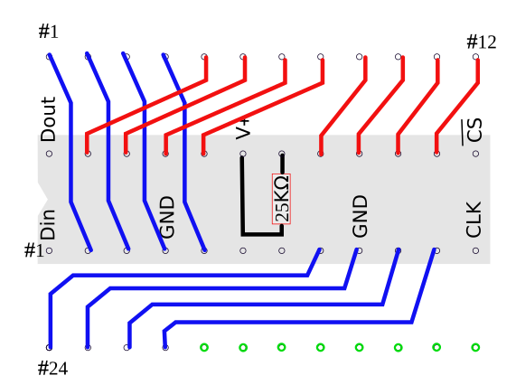
Today I managed to get the layout done.
The wiring schematic is very simple - one chip pinput to neares LED Matrix pin.
As the chip pinout is not straight 1,2,3 the ordering of segment/columns will be "slightly" random, so the software will need to map logical row/colum to real ones.
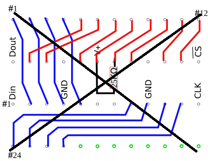
EDIT - "typo" or what you call it when there is an obvious error in the drawing. This was/is just done in Inkscape, more of a drawing/sketch than a diagram It should of course be (I've also clarified what is the chip)
BTW, the 8x8 matrix I have are Bi-colour (Red/Green; meaning I can show Black, Green, Yellow, Red) but that would require 4 MAX7219 and I only bought 3, so it remains Red like the simulation model.
Discussions
Become a Hackaday.io Member
Create an account to leave a comment. Already have an account? Log In.