 WingTechCorner
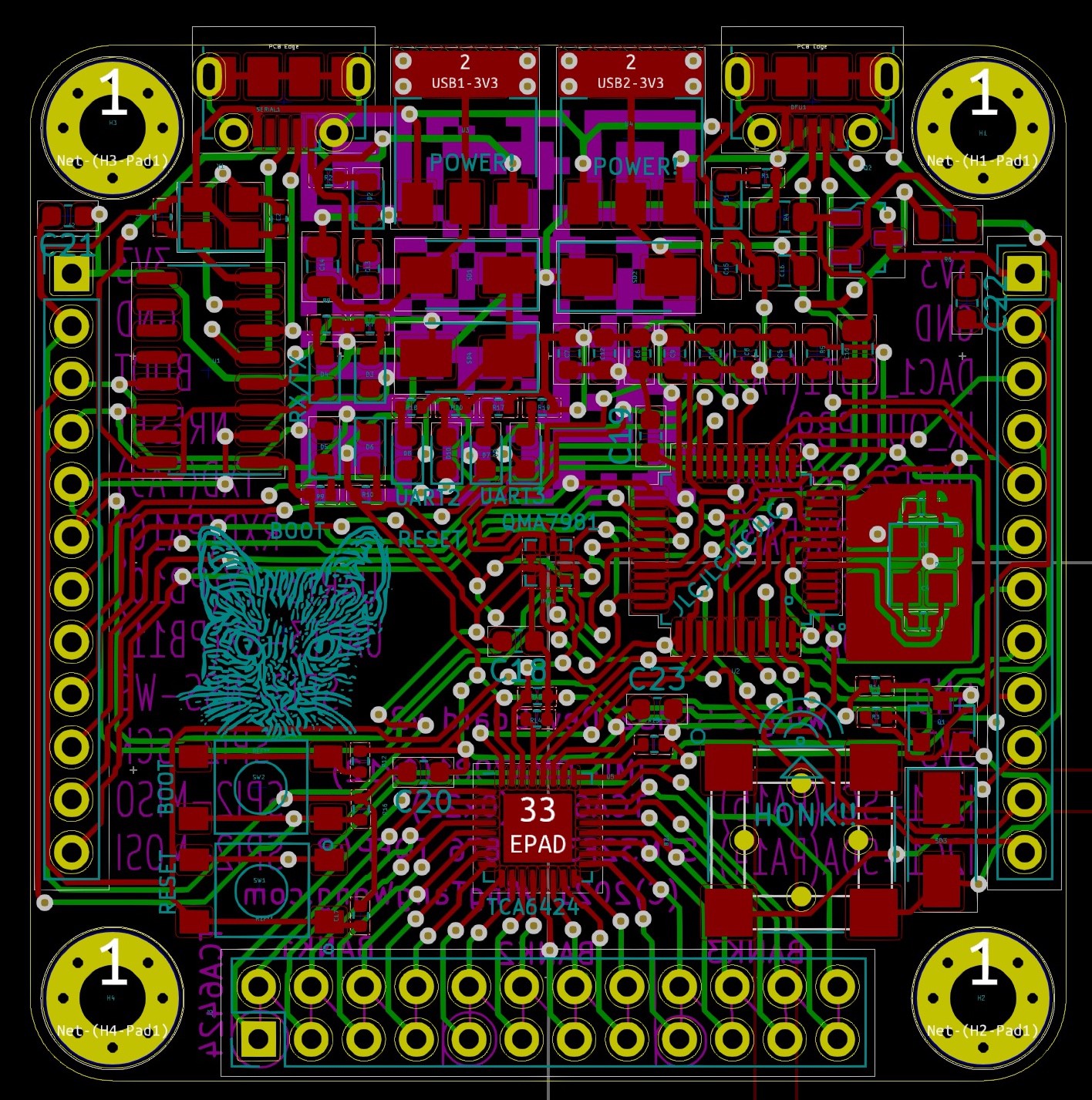
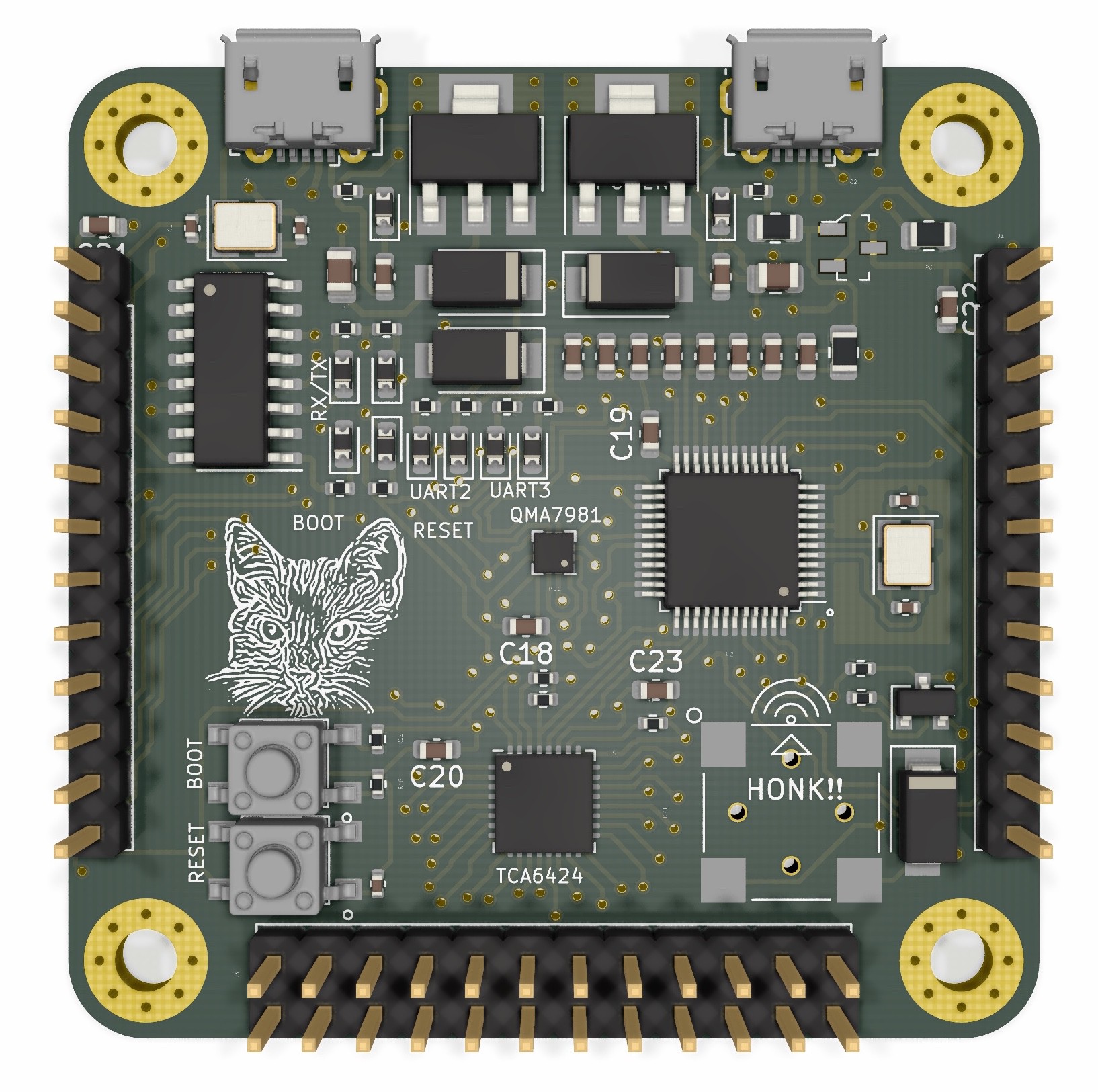
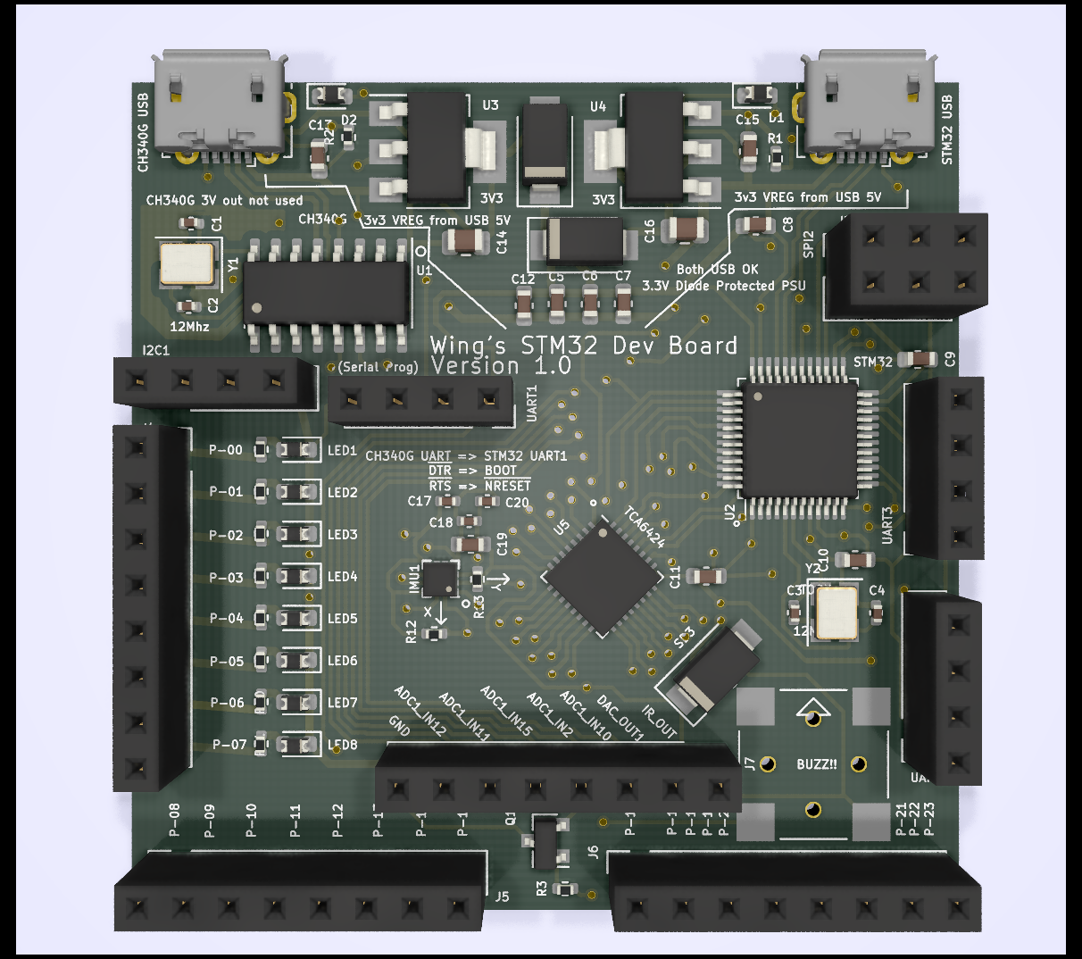
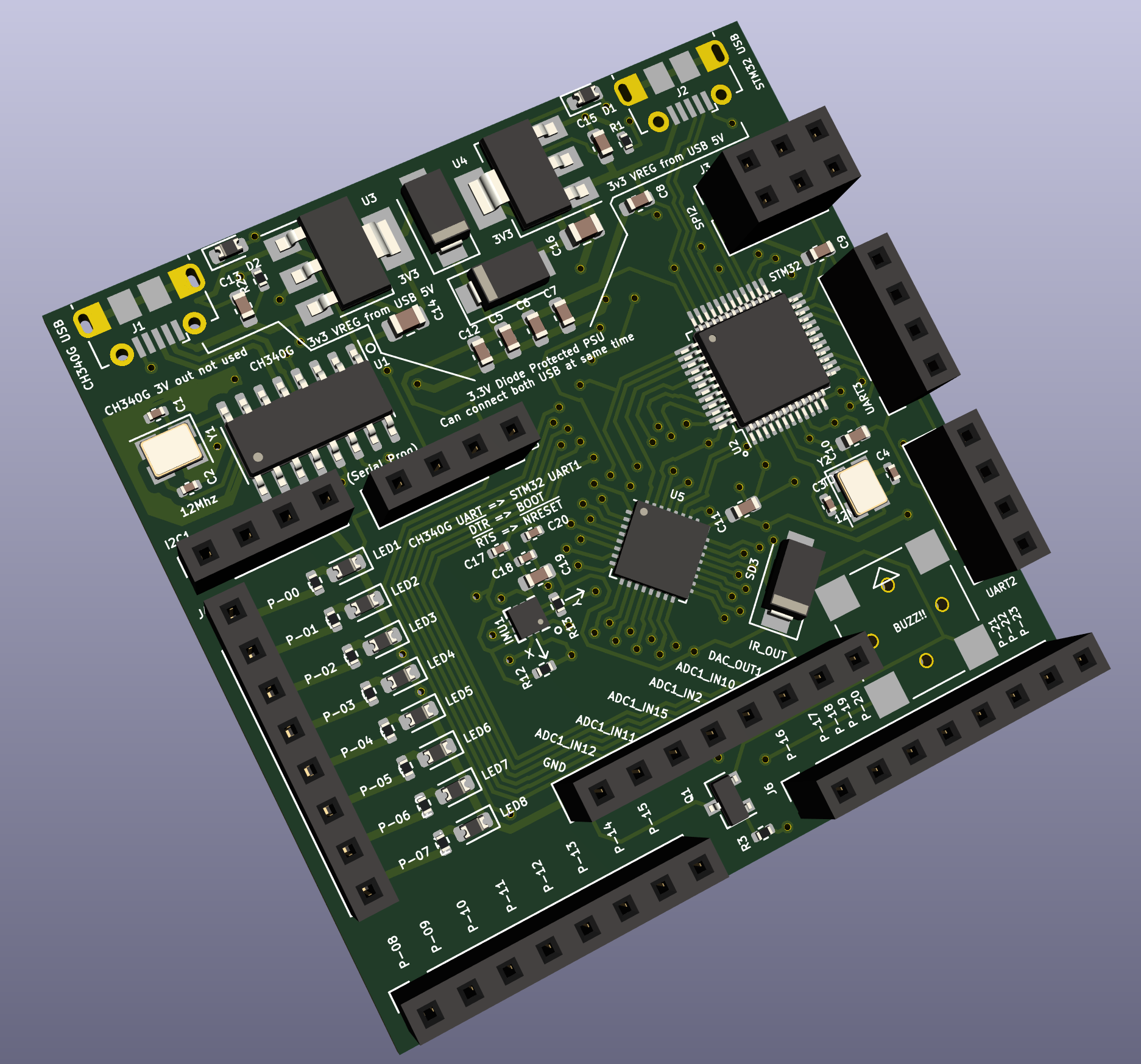
- Reproduce the typical USB => USB/UART IC => STM32 programming flow.
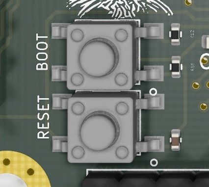
- This involves the control of the BOOT and nRESET pins. This is normally facilitated via DTR/RTS.
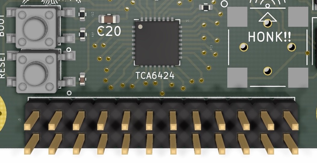
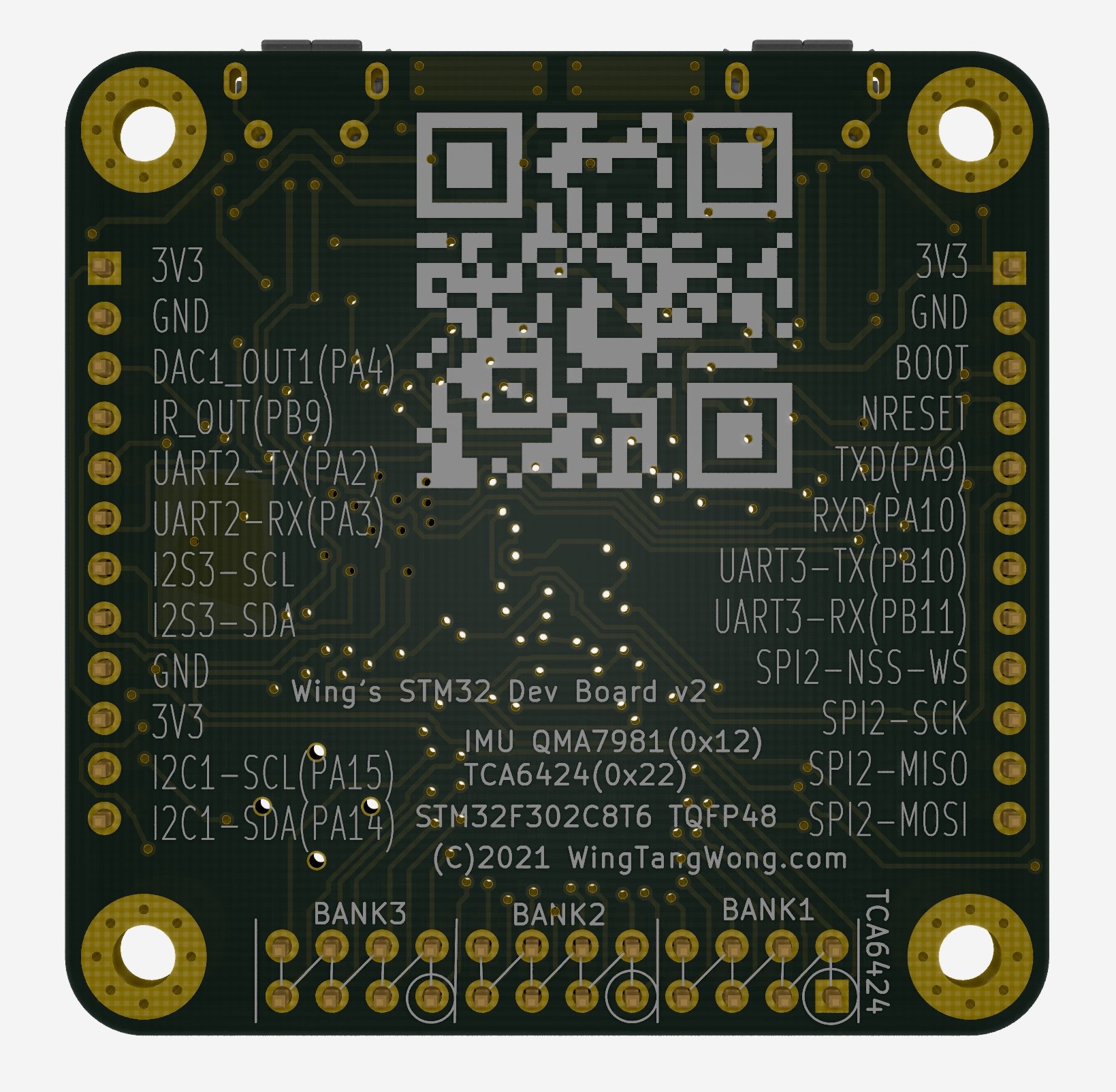
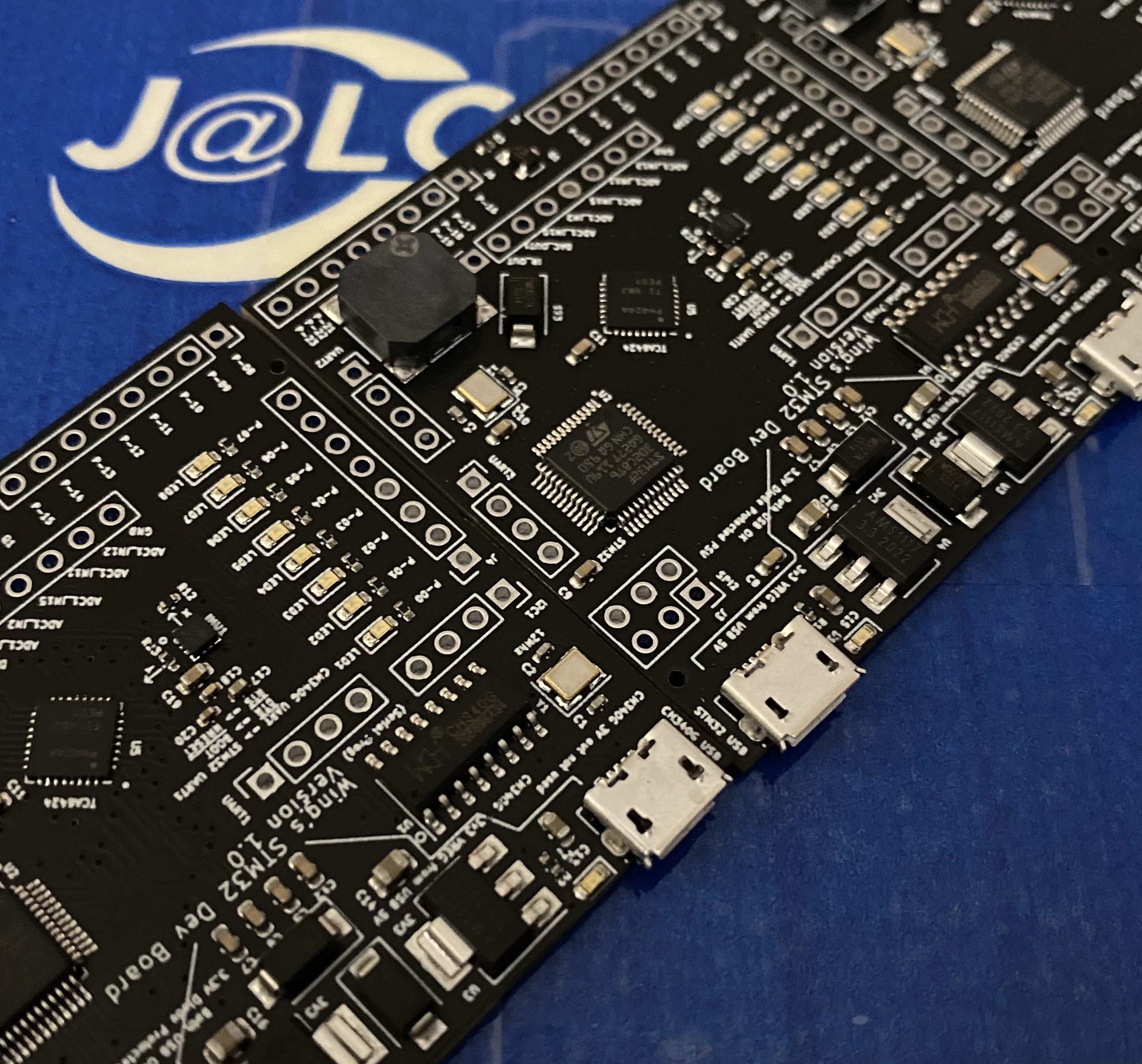
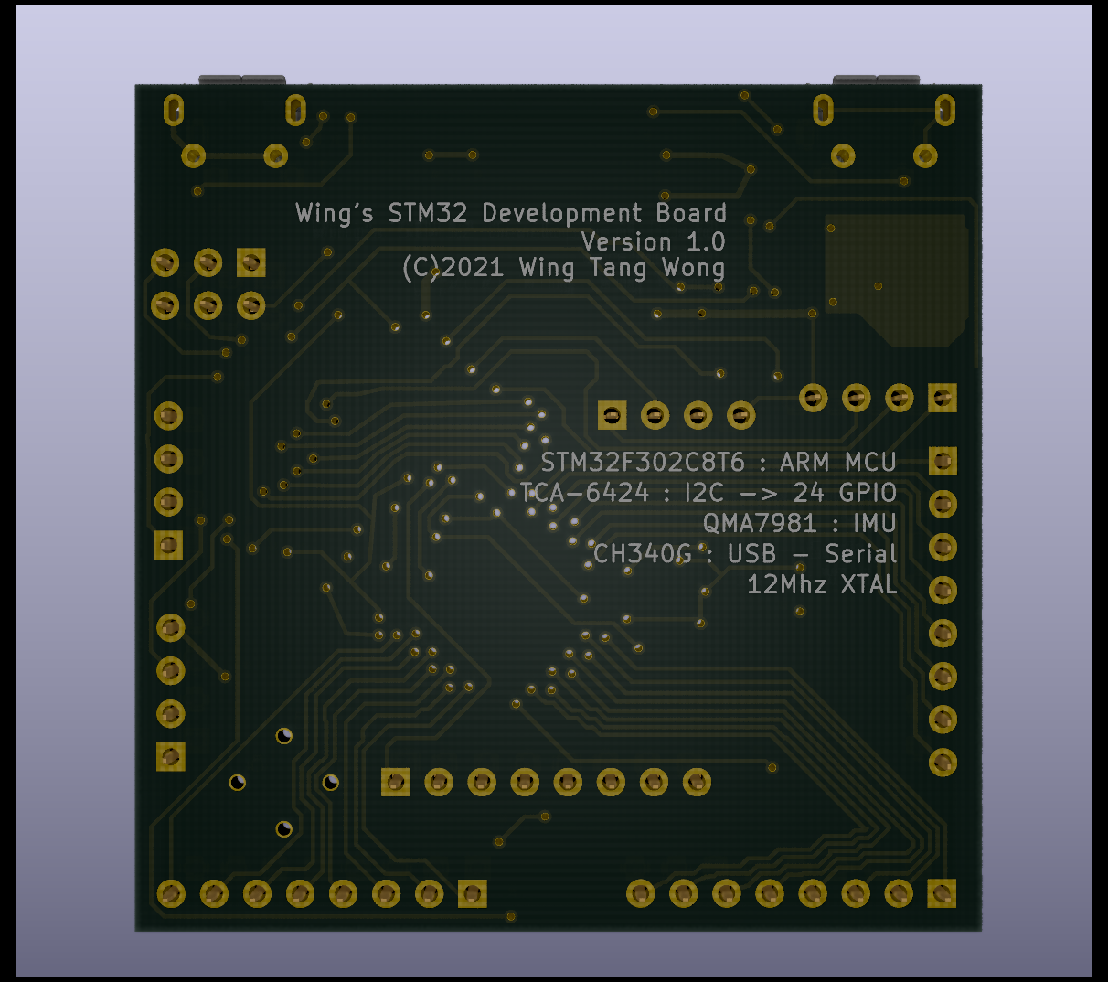
- Provide LOTS of GPIO for the STM32 IC in the form of an expander. TCA6424 in this case.
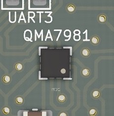
- Provide a sensor. An IMUU in this case.
- Provide a breakout for the communication channels on the STM32.
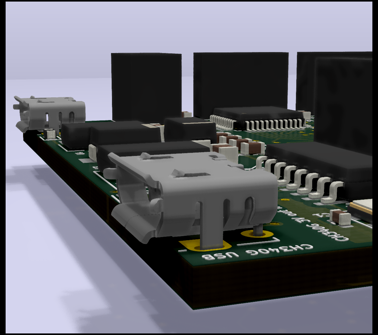
- Provide a means of having multiple concurrent USB/power sources plugged in without things going _boom_.
0%
0%
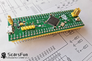
Wing's STM32 Dev Board
A small project to build a STM32 development board using KiCad
Become a Hackaday.io member
Already have an account? Log in.
Just one more thing
To make the experience fit your profile, pick a username and tell us what interests you.
Pick an awesome username
hackaday.io/
Your profile's URL: hackaday.io/username. Max 25 alphanumeric characters.
Pick a few interests
Projects that share your interests
People that share your interests
 Alexander Mandera
 ScarsFun
 Jakub Piasecki
Great Design !
One Question though, how do you connect the CH340G to the STM32?