 P
PBeen thinking about how to efficiently stack 4 4-channel boards to get to 16 channels. I think I'm getting close to a solution that will allow me to use 4 identical boards (so I don't have to get 4 separate boards manufactured), and use DIP switches to set an address for each board.
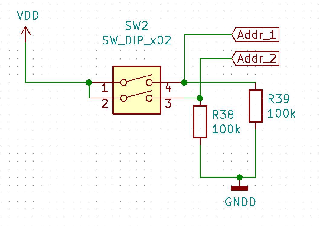
Essentially, the 2 DIP switches will set a unique binary address between 0 and 3 for each board:
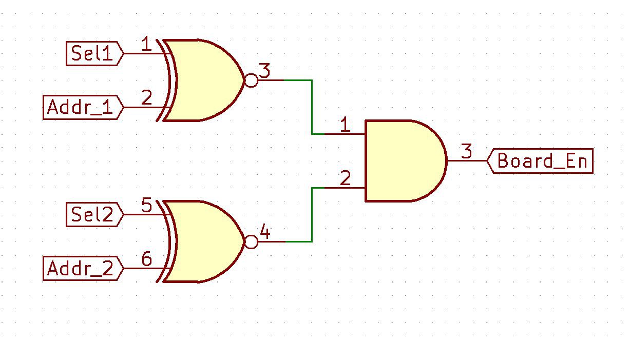
Then that address will be XNOR'd with SEL1 and SEL2 signals coming from the ESP32 to generate a logic-high 'Board Enable' signal if that board's address is selected:
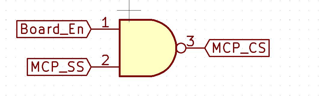
and the Board Enable signal will then be NAND'd with the MCP SS signal coming from the ESP32 (which now will have to be logic high), to generate the logic-low MCP_CS signal if that board is enabled:
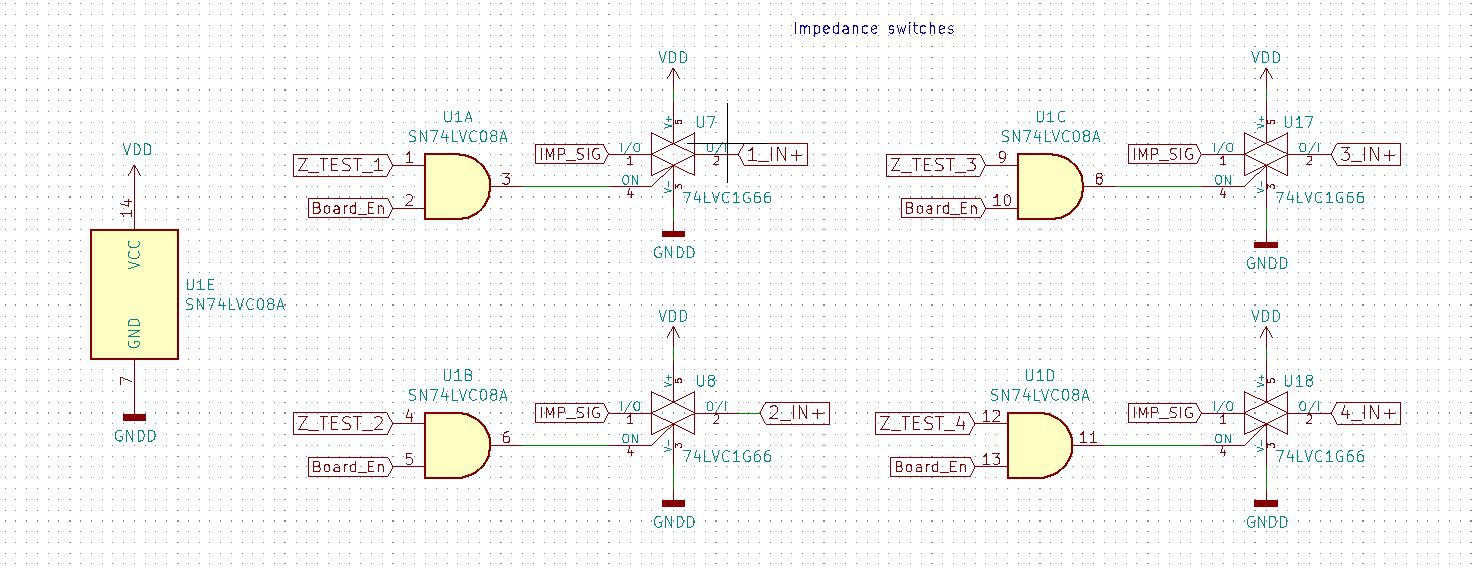
The Board Enable signal will also be AND'd with the logic-high Z_TEST signals from ESP32 to select the correct channel for impedance measurement when the board is enabled:
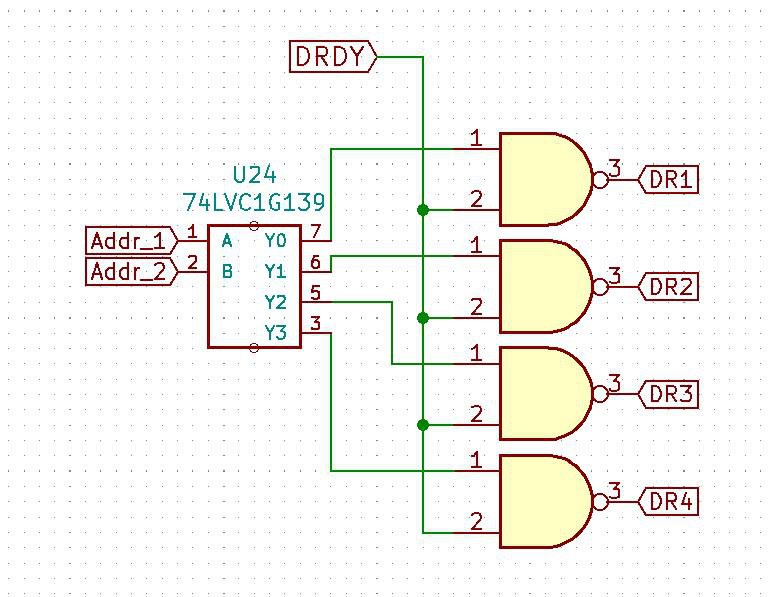
Finally, the Address signals will be fed to a 2-4 decoder and NAND'd with the DRDY signal (logic low) to create a logic high pulse on the DR line of the selected address. Using open drain gates here meant that I needed NAND gates and therefore had to invert the DRDY signal, since all the boards will have a gate output connected to each DR pin (but only the board with the proper address will toggle that pin), and therefore if they all sat at ground while inactive (i.e. using an AND gate), the active gate wouldn't be able to toggle the pin:
 But with those small changes I should be able to then stack the boards and use just 2 address lines to enable the proper board for sampling or impedance measurement. So instead of needing 16 (impedance switches) + 4 (MCP_SSs) + 3 (MISO/MOSI/SCK) = 23 GPIOs, I can get away with just 2 (select lines) + 4 (impedance switches) + 1 (MCP_SS) + 3 (MISO/MOSI/SCK) = 10 GPIOs.
The DRDY pins each need their own GPIO pin interrupt, so there was no way to combine them (but the ESP32 does have 4 digital input-only pins which would make sense to use for these signals) and I'll need 2 additional GPIOs for the DAC_SS and reference channel impedance switch, bringing the total GPIOs needed to 16, plus 1 ADC for the impedance measurement. I'm not completely sure, but I think that should be doable with most generic ESP32 dev boards. I'm still debating whether to use an off-the-shelf dev board with a custom interposer board, or to design my own ESP32 breakout board, and I think I'm starting to lean towards making my own.
Discussions
Become a Hackaday.io Member
Create an account to leave a comment. Already have an account? Log In.