The real purpose of the project is to develop a pair of reusable modules. One module for accurate time acquisition and the other for general purpose computation.
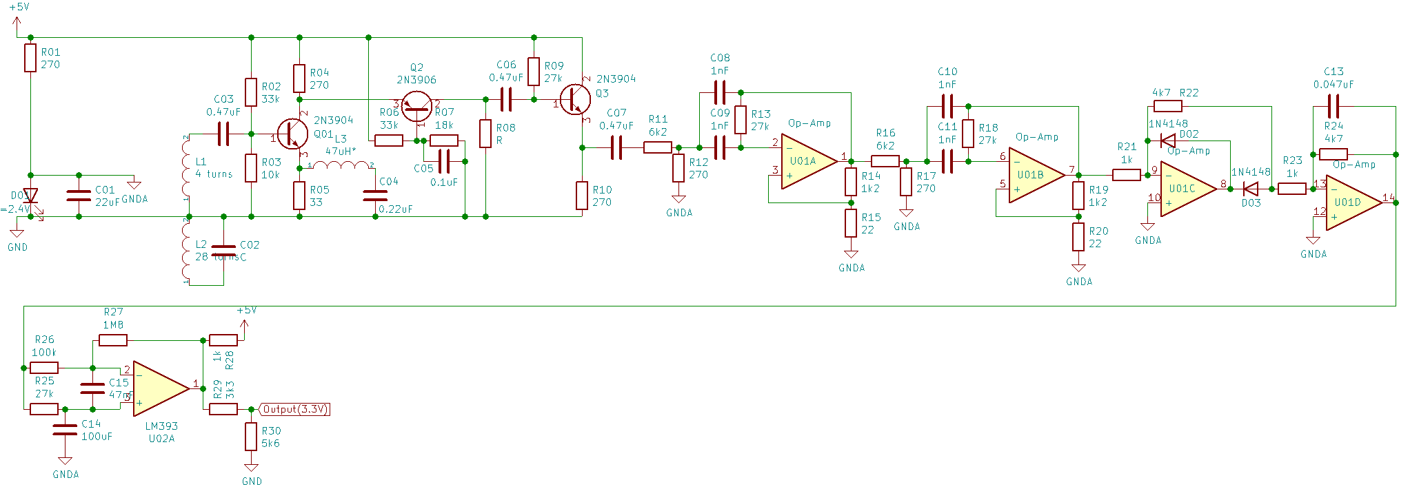
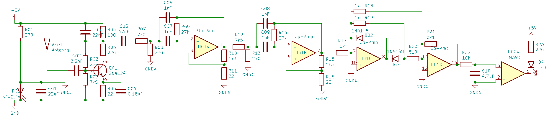
This time module tunes in to the WWVB signal at 60kHz and outputs an encoded digital stream. At the moment, the antenna is little more than a coiled up ethernet cable with a capacitor soldered to each end. Really, that's all it is. The signal from the antenna is amplified by a complementary transistor pair in a folded cascode configuration and passed on to an op-amp analog filter and an op-amp rectifier. A comparator then decides whether the WWVB carrier is at its high amplitude or low amplitude.
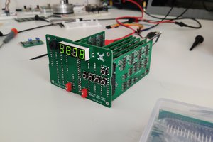
The pulse width modulated time signal triggers a 74x221 and a 555 oscillator to control a 74x93 counter. The 555 oscillates at 10Hz, and the 221's time interval is about 0.9 seconds. The result is that the counter will show a final count of 2, 5, or 8 before being reset. (Let's disregard noise in the signal, for now.) Those values correspond to 0.2, 0.5 and 0.8 second modulation durations that are transmitted. A miniscule amount processing can turn that stream of digits in to the current time and date.
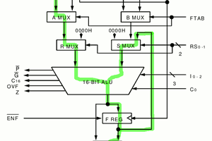
The Turing machine decoder is nearing completion, so there's only an overview for now. The 'tape' consists of an 8 bit up/down counter and a 256x4 SRAM. Those 4 bits are combined with 8 'state' bits held in a latch. Four bits are available to select the time zone offset, daylight saving flag, and display options. One last bit is used to select a high or low address in an EPROM. The 16 bit output then updates the state, writes a new value to the tape, and selects which data source (WWVB or tape) is in use.
 Yann Guidon / YGDES
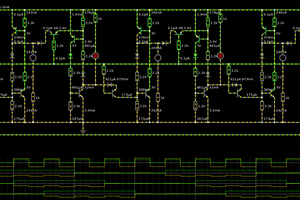
 Eric Ljungquist