RS485 communication is usually performed by UARTs sharing a common differential pair of wires. Only one UART can drive (send) data at the time, the other participans may listen in as they wish. An RS485 driver sits between the UART transmitter output and the common RS485 cable. This driver must be switched on before transmission and off just after. Thereafter an other node may send their message, often as a reply to the first.
Some micro controllers have hardware that can be configured to drive a pin used for this switchover, alternatively the program can drive a pin high and low as needed. The problem with the software solution is that interrupts can occur which delays the switching. The delay can be long for controllers with operating systems, like Raspberry PI and Beaglebone. Between the last bit sent and when the software gets access to the pin the OS can be busy with quite different tasks. The gap between messages must be longer than this delay else two nodes will be driving the line and corrupted data will be the result. So, for efficient and predictable communication qualities, some external hardware is needed.
For properly terminated RS485 cables it is early enough to turn on the driver at the high to low transition of the start bit. There after the signal can be held active for some time longer than is takes to transmit the start bit and data bits. Allowing for some tolerances it is good practice to turn the signal off at the middle of the stop bit. So the signal will optimally be on for 9.5 bit-times when transmitting 8-bit data. I use an 115200 bit/sec bit rate, so the 9.5 bit time translates into 82.5 usec.
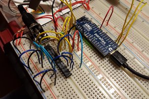
I implemented this in an AtMega202 micro controller . I configured the program using https://start.atmel.com, and haven't peeked into the generated code. An input pin connected to the UART transmit signal generates an event when the pin goes low at the start-bit. This event then starts a TCB timer running in mono stable mode. The output of the timer immediately drives the WO pin high until the programmed time has elapsed. The mono stable mode is not re-triggerable, so the counter only reacts to the start bit.which comes in an eight pin SO package and costs less than half an USD.
This works fine, as the oscilloscope images from my breadboard shows. The UART signal at the top and driver enable signal at the bottom. One image shows the transmission of two 'U's. The other one the delay at the start bit transition. The delay seems to be around 20 nsec.
If you want to have a look at the program you can open https://cdn.hackaday.io/files/1780857619188640/rs485-202.atzip in the start.atmel web page.
This will not work if we want to also allow for break signalling. In that case the condition for releasing the driver signal will be to wait until the nominal time has elapsed and the UART signal is high. This can perhaps be implemented with the help of the controller's Digital Glue Logic. If you need break signaling you can also use another microchip controller as published by Ward Brown in Electronic Design.

 Kevin LO
 Jac Goudsmit