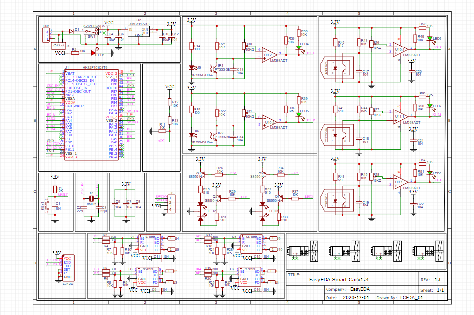
Function introduction
(1) The power supply of the smart car is a 7.4V lithium battery, and the anti-reverse connection design is well done;
(2) On-board power check circuit to realize low voltage alarm function;
(3) The RZ7899 is used to drive the N20 DC motor, and the software simulates PWM to control the motor speed;
(4) Infrared and obstacle avoidance are realized by two different infrared tube schemes, and a comparator circuit is designed with an operational amplifier.
(5) Two headlights are added in the front, which will flash in an emergency to simulate the function of the car;
(6) The interface of the 2.4G wireless communication module is reserved to facilitate the extension of wireless control function in the later stage;
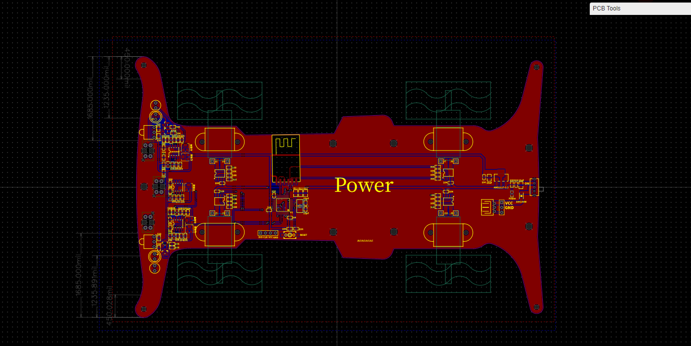
(7) The car has a matching 3D shell file to facilitate the design of a customized shell.
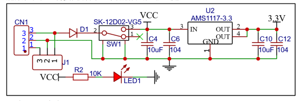
Power input circuit
The power supply of the smart car is a 7.4V lithium battery power supply, increase the anti-reverse connection design of the diode.
Through AMS1117-3.3V step-down power supply to the microcontroller, LED1 is the power indicator.
If you want to pursue a higher performance of the car, you can replace it with a switching power circuit to strengthen heat dissipation.
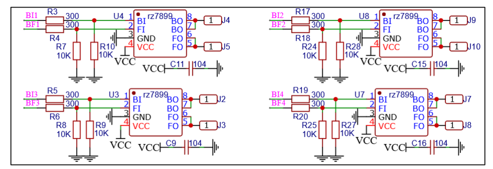
Power drive circuit
The motor circuit uses the RZ7899 chip, which is suitable for automatic valve motor drives, electromagnetic door lock drives, and other application circuits. It controls the motor forward, backward, and braking by the logical input ports BI and FI, and the motor speed can be controlled by the PWM output of the single-chip microcomputer. The application circuit has good anti-interference ability, a small standby current, low output resistance, and other excellent functions. Note that a 104 chip capacitor is connected in parallel to the motor during welding. Of course, if you have a better idea can change a drive circuit to make the car more powerful!
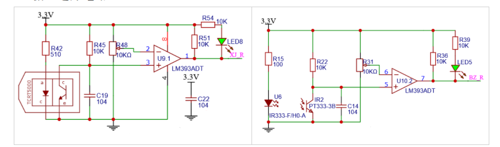
Tracking and obstacle avoidance circuits
The tracking and obstacle avoidance circuits are designed by an LM393 voltage comparator and infrared tube. When the infrared receiving tube receives the reflected signal, the forward input voltage of the op-amp is close to 0, and the output level is low through the comparator. At this time, the LED and so on are lit.
The pin condition of the IO port is detected by the MCU pin so that the car can walk along the black line and move forward to avoid obstacles.
Lamp circuit
The car lamp circuit uses a two-color LED lamp and gets controlled by PNP triode.

PCB Prototype by JLCPCB Now the SMT service is set up fee-free and many coupons for SMT service

 kamalkedin123
 DIY GUY Chris
 Silícios Lab