 techknight
After completing the schematic and architecture of the I/O card, It is time to take a look at the ROM.
With how unique the bus interface logic is back to the 68K, essentially using a PIO and a few other things to mesh with the 68K read/write cycles from the MCS51, I just had to take a look at the routines and document how they pulled this off.
A quick study of the bus interface logic, reveals a PAL which acts as an address decoder. This address decoder is tied to INT0 and INT1 of the CPU:
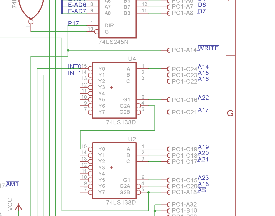
This helps aid in finding where those routines are in ROM. Digging through ROM, I was able to locate the routines:
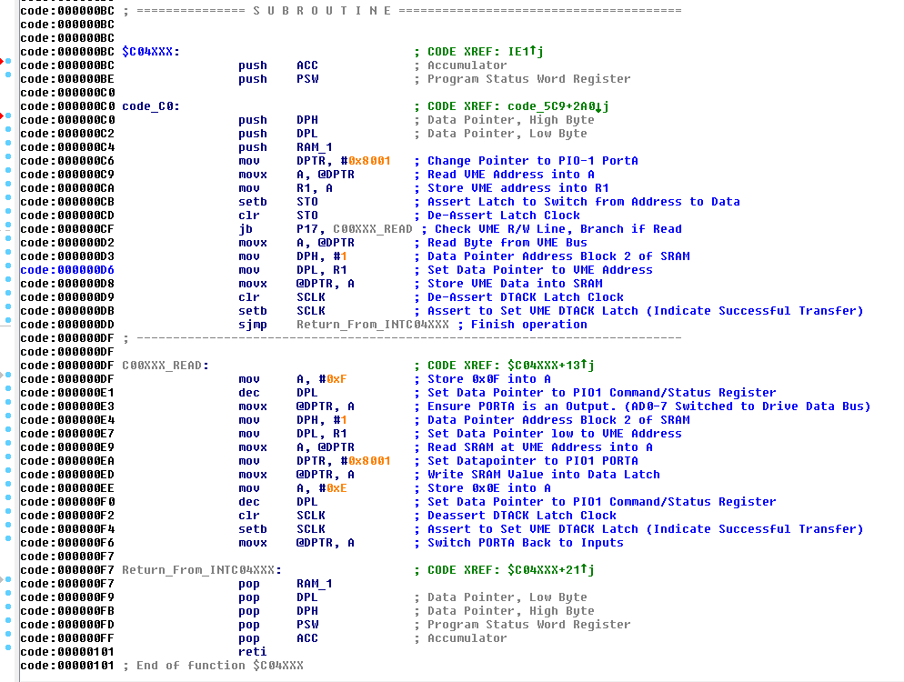
The above subroutine is INT1, which is decoded at the address space I had commented in the above code. It is a fairly clever subroutine!
I commented all of the ASM code to better understand what is going on with the above subroutine. It may not be 100% accurate, but its as close as I can get it.
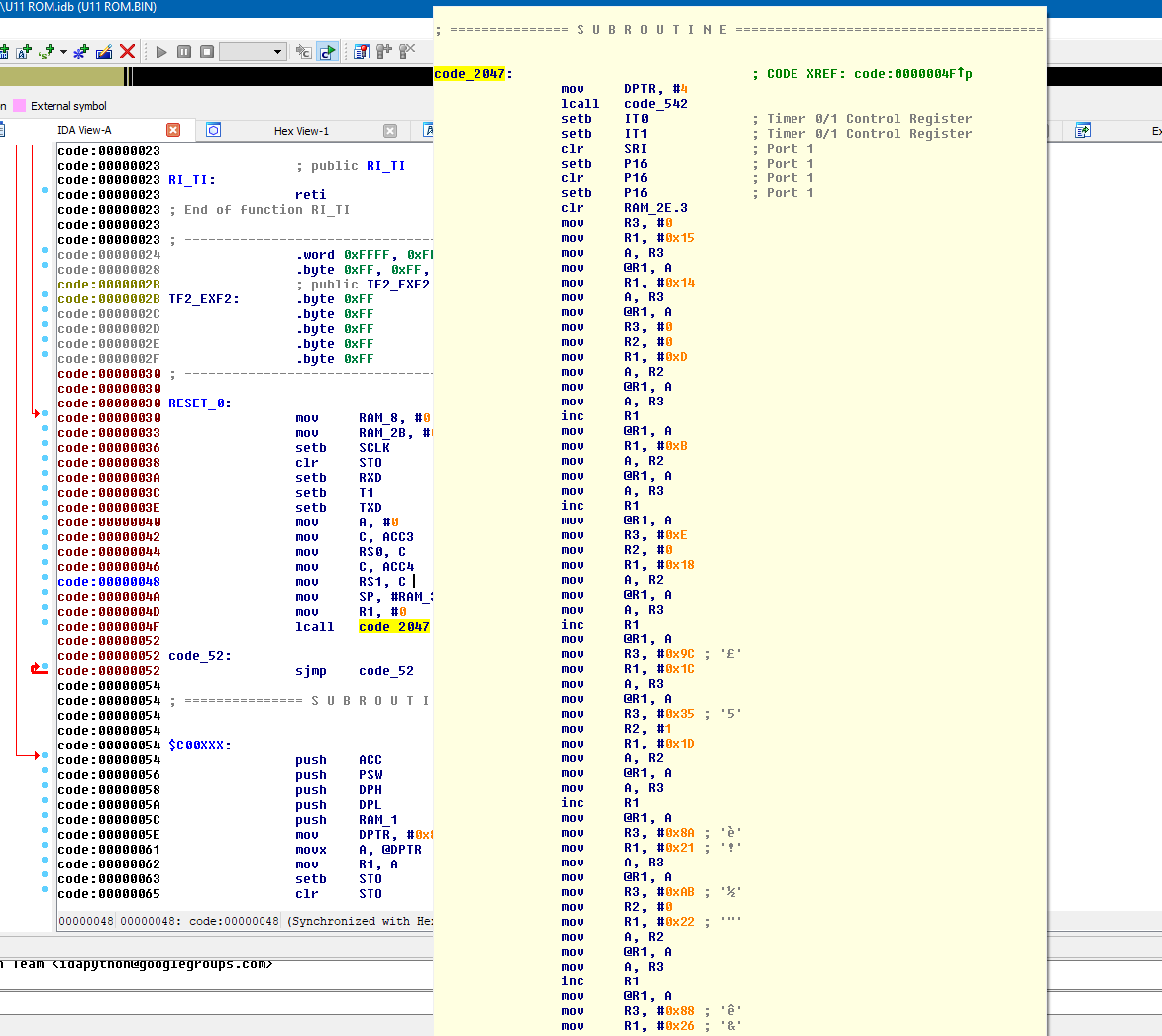
The INT0 routine is a bit longer, as its doing some other stuff.
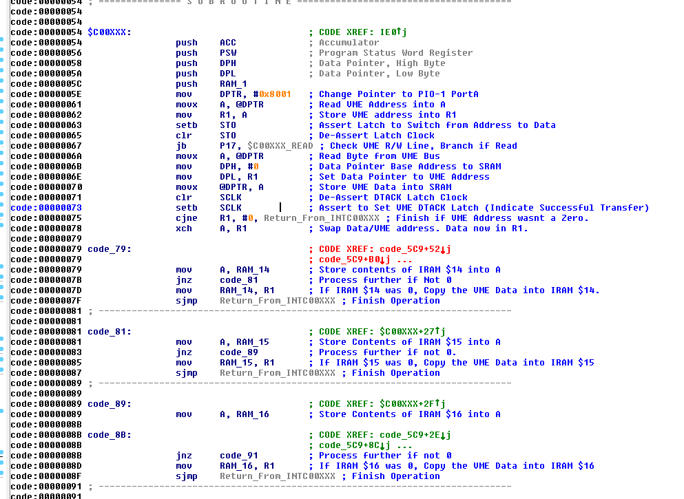
As we can see, the C0XXXX code is much larger, and it has additional checks in it. I am going to assume at this point, this is where the commands to actually control the card are sent. whereas the INT1 handler might just be for data only. But your guess would be about as bad as mine.
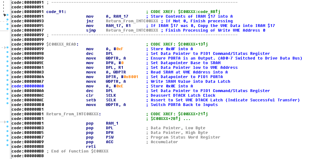
At this point, we have somewhere to start at least. Since INT0/INT1 are the only way the 68K can speak to this card, we can assume the command processor has to be triggered from this as well. you can see where it reads 4 bytes into 0x14-0x17 in the CPU's RAM space. So we must find the routine that handles all of this outside of the interrupt in order to learn how to control this card in the method they proposed.
So to help try and find this, Lets take a look at the RESET vector:
As you can see with the above, we have basic initialization code for the registers and RAM, a call to a code block at 2047, and then a branch always loop at code_52. so it just sits there indefinitely.
That clues us in that this device is entirely interrupt driven. Now, bear in mind this device also has to run a modem, AT keyboard, and a host of other things.
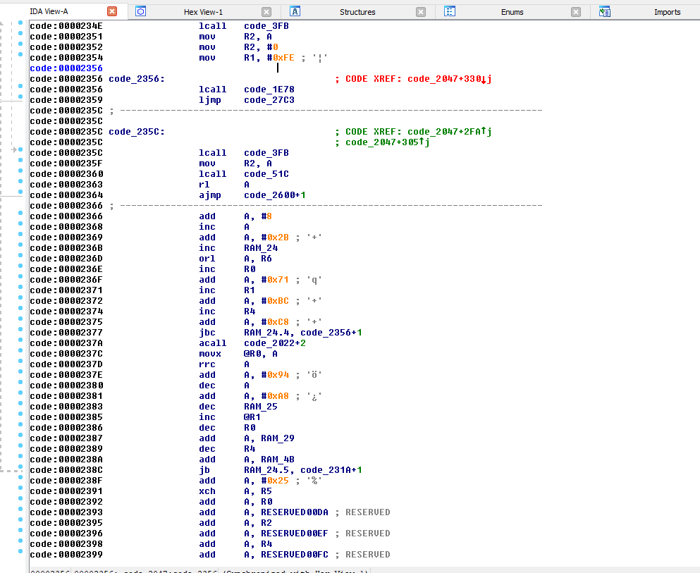
But the problem begins with the code block at 2047. its literally a nightmare scenario, and its super hard to follow as it goes through.
If we take a look at the timer interrupt, we have this:
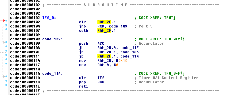
And that's it, all it does. Appears to be settings/clearing flags and changing some things in RAM, however I do not know precisely what its actually doing. It might be related to the modem or AT keyboard. since they are using the same UART on the CPU for both the modem, and the AT keyboard it could be related to both. Who knows...
However, with all of that said I fail to see how it catches and processes data from the bus. this code is super hard to follow. For example, that code block called from RESET just goes on and on and on forever:
So instead of spending days and days and days trying to chase this code since theres no examples on how to use the API of this ROM, I had to make a decision to abandon the ROM entirely and just write my own thing to save grace here, I could also avoid writing the routines for the modem, and AT keyboard since I did not need either of them. I only wanted the LEDs, the RS232 port, and general purpose I/O.
The main code block are literally ljmp ops all over the place, back and forth. they arnt using any rts or jsrs, its the epitome of spaghetti code...
Hence, trouble in paradise...
Discussions
Become a Hackaday.io Member
Create an account to leave a comment. Already have an account? Log In.