 techknight
Now that we are able to draw images into the framebuffer, we basically have the graphics card under our belt now. Except for one thing....
Framebuffer control. We briefly touched on this in a previous blog entry, but now its time to go into some more detail.
Thing is, we can draw images into the framebuffer that is being displayed, but unfortunately drawing is fairly slow. so you would see the drawing process on screen.
So, to prevent this from happening and to provide a better experience to the viewer, we need to double buffer the drawing. The way to do this is simply drawing graphics/text into other areas of RAM that are not currently visible on the screen.
This is going to require more experimentation and studying of one of the most important commands. CMD01.
This command not only contains the Palette data thats sent, it also contains up to 3 framebuffer window settings. So, you can have up to 3 different set viewport partitions on screen at the same time. Plus there is CMD06 which is an overlay window that comes up from the bottom on a specified height.
from Studying the ROM, this was my initial analysis on the CMD01:
===============================================================================================================================================
Command $01: (Ex: 01 00 FF 00 00 01 00 00 00 00 )
Byte 1 gets copied into a couple other registers before manipulated and written into the FPGA.
Byte 1.0 = Enable/Disable Local Video
Byte 1.1 = Does a multiply by 2 on the counters. (Maybe switch active pages)
Byte 1.2 = Disable/Enable Graphics Output. When disabled, Ends CMD01 processing entirely. (Set to Disable, MUST be last byte when Set!)
Byte 1.3 = Does the same thing as Byte 1.1 (MAybe at different times though)
--
Byte 2 (Switches Output Resolution)
0 = 384x120
1 = 384x240
2 = 768x240
3 = 768x480
Byte 2.0 = Sets/Clears $22.1
Byte 2.1 = Sets/Clears $20.6, and $28.3
-------------------------------------------------------------------------------------
Byte 3
Condition Flag whether to do a full Palette Copy and Counters signaling copy.
If 0 We skip Palette load, and Read Byte 4.

Byte 4 if Byte 3 = 0
Condition flag whether we copy animate data or not.
If 0, we skip animation info and go into copy data into 0x710. Return from cMD01.
-------------------------------------------------------------------------------------
-------------------------------------------------------------------------------------
Byte 3
If 1 then we load the palette1 with data. A full 0x0300 byte load is EXPECTED/REQUIRED!

Byte 4 if Byte 3 was 1.
Still serves the same purpose, with an addition.
IF 0, We skip the animation info and go into the copy data into 0x710. BUT, Now, after that, the recently loaded Palette gets copied into RAMDAC. End CMD08
-------------------------------------------------------------------------------------
If Byte 4 > 0 in either case, it loads the appropriate info for Palette animation.
Byte 4 = Number of Blocks of color palette to animate. Each Block is 7 Colors.
Each byte after this is each block location. Last byte is the speed at which the animation occurs.

================================================================================================================================================
Sorry if the above is confusing, but it was my quick analysis at the time. But it will get a bit more clear the further we go on.
Now, if we put 768x480 images in framebuffer, we only have enough RAM for maybe 4 of those images. We already know from watching in the past that the radar is at least 6 frames of animation. These frames are obviously not drawn in real-time because it would be too slow. So its definitely pre-rendered into RAM, and the pointers move around to point where each image has been drawn in VRAM.
So in order to do this, the machine has to switch resolutions to a lower resolution so we can "fit more" into memory.
Thus enters Byte 2. This byte seems to change the resolution of the output.
The way the lower resolutions work, is it takes the full 768 pixel line and splits it into two halves. so the second group of 384 pixels (on the right side) show up 1 line below the first set. So basically like Even/Odd lines.
As pictured here:
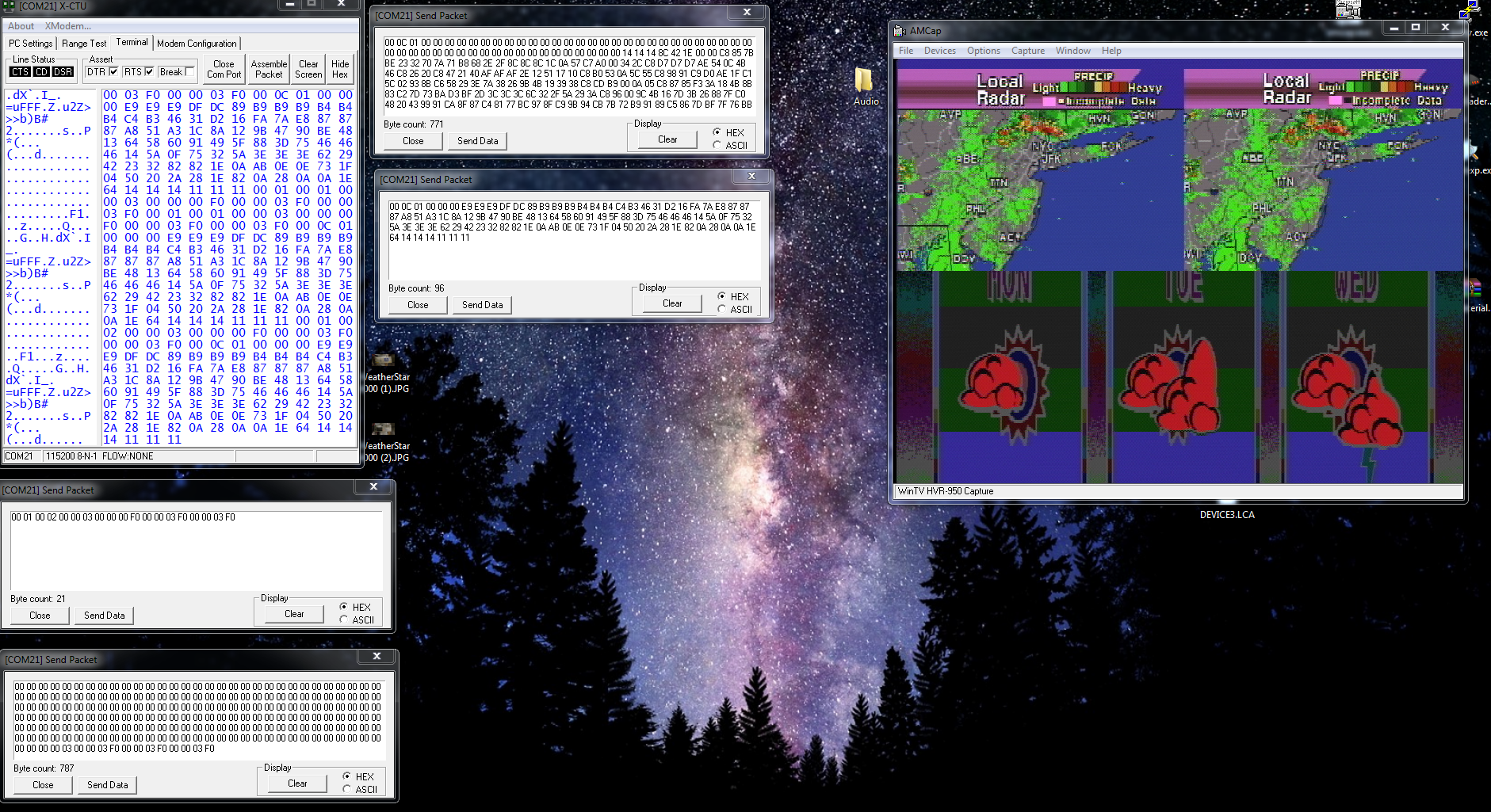
I sent the radar image and switched the Palette to the Radar color palette.
You quickly notice that the image appears to be split in two. This is the odd/even line that I was talking about. the 2nd line of the image is drawn to the immediate right of the 1st line. This essentially allows you to double your framebuffer space or even 4x your framebuffer space for lower resolutions.
This is how radar was accomplished.
So. Modifying byte 2 to set the framebuffer to 384x240, yields this:
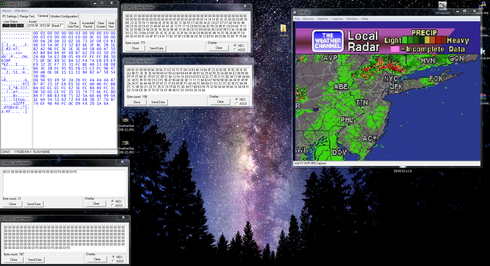
Perfect. that image looks normal. And its occupying only 384x240 in framebuffer, but.... its technically 120 lines of 768 pixels as i explained earlier.
Confused yet? Good! :-)
In the next part, we will talk about the framebuffer pointers and how we achieve which section of memory is show on screen.
Discussions
Become a Hackaday.io Member
Create an account to leave a comment. Already have an account? Log In.