 techknight
As we discussed in the previous installment, we can switch resolutions and send color palettes via the CMD01 being sent to framebuffer control.
Now, as we discussed there must be a way to be able to change where the on-screen viewport points to in memory.
When discovering the command, I found this in ROM:

To most people, this doesnt mean much. But... This is called on startup very early in the process as that 8051 ROM boots. the location in RAM 0x710 is the same areas where CMD01 configures for its viewports.
With that known, the above basically gives us an initial state the framebuffer is during startup. So with my analysis of CMD01 in the previous installment, lets take a peek at ROM to figure out the code flow and see how the viewports are configured.
Looking at the startup code, its looped 3 times. So thats something to keep in mind for going forward.
One thing that clued me in however, was from a conversation we had with Michael Searce. He had mentioned the WS4000 had at least 3 framebuffers that can be shown on screen at any point in time. Aha. So.... lets follow the code-flow to confirm our suspicions.
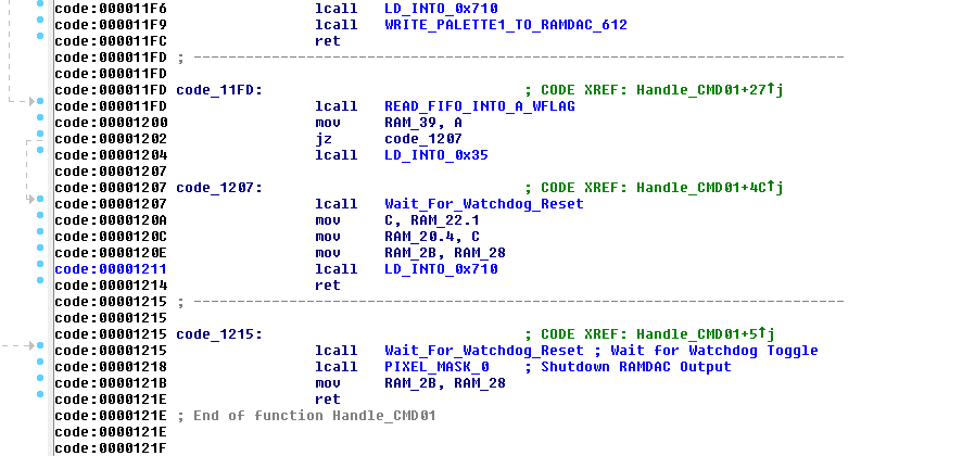
If we thumb through the CMD 01 handler, we can see towards the bottom here our familiar memory location 0x710 that I have labeled. So, lets take a look at that subroutine.
So if we follow this code, First off it reads a byte from the FIFO and stores it into Register 2. Then it sets the DPTR to point to 0x710 in RAM. It then reads 4 bytes from the FIFO, then performs a calculation whether it sets the 5th byte 0x30 or 0x60, but it is not read from the FIFO so it does not matter here.
Then.... you encounter the djnz instruction. This Decrements R2, and if its not Zero, it will jump off back to $0x13A5 which reads another block of 4 bytes.
So given this, it certainly confirms the information Mike has supplied about having multiple framebuffers. Trouble is, there are no boundary checks so technically you could copy 4 byte blocks 255 times. That.... would be bad because you will corrupt the rest of SRAM, and then run out of it! So.... don't do that.
So.... if we reference what we see in the above code, versus the example byte values in the Startup code, we can make a reasonable assumption of what to send it.
We can now formulate an example command:
01 02 03 00 00 01 00 00 00 F0
So lets break this down a bit:
01 = Command 01
02 = Enable Graphics Output
03 = Resolution (768x480)
00 = Send Palette
00 = Send Animation
01 = Number of 4 byte viewport blocks
00 = Viewport Byte 1
00 = Viewport Byte 2
00 = Viewport Byte 3
F0 = Viewport Byte 4
So this is what we know so far. Not much at this point, I know. But at least we have something to start with. And matter of fact, This is the command I used initially to get graphics to show up on the output at all as this was critical.
So at this point its a process of elimination. Try changing byte values and see what the hell happens. But before we do that, lets take a look at the value F0 at the end
This was the value that was in in ROM to begin with as an initial setting, so there must be some significance to this. So lets take an educated guess on what that means. So the first thing we should to is convert the 0xF0 to Decimal, which is: 240. Huh interesting. My mind is trained to see patterns so knowing the framebuffer height is 480, its awful convenient that this value is 240.
So, I must assume 0xF0 is the Viewport height Divided by 2. so if we multiply the decimal equivalent of 0xF0, we get 480. Magic....
So that just leaves 3 values that are unknown at this point. Sending this command as it is will use the default SMPTE Palette that is built into ROM, and show a 768x480 image of whatever is sitting framebuffer.
So the next step in this process is lets get something drawn into the framebuffer. We start with something like this:
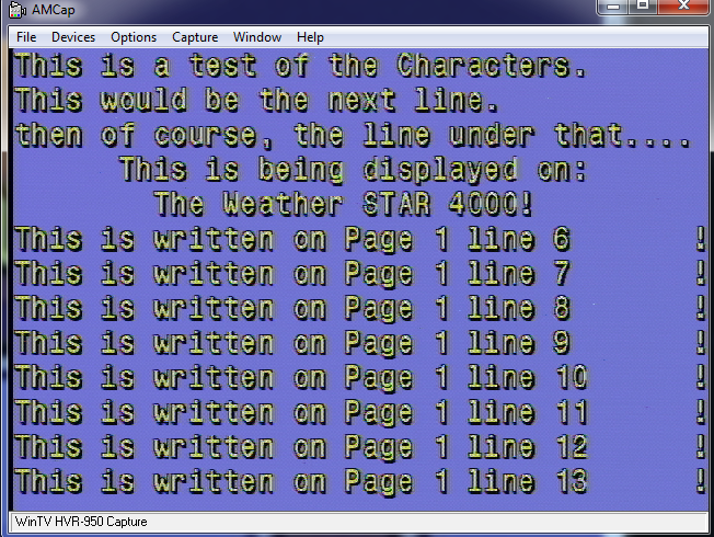
So what we did here was simply draw some text on the screen. This will give me a reference where I am at in the framebuffer before I get lost.
To understand this: Page 1 means the first 480 lines of framebuffer memory. Line 481 would be "Page 2". this will help me identify where I am at in RAM. and of course the Line numbers are self explanatory. Each line is 36 pixels tall so i can easily to the math.
So.... Lets change the first byte value and see what happens:

Woah! it appears modifying the byte jumps the position of the text over, and it kinda "Wraps around" Ok.... what does that mean? I gotta sit and think about it for a bit.
I don't have any footage of my experimentation to know what value jumps it by how much. What I have figured out, is the first TWO byte are little-endian formatted "offset" at which pixel will be the start pixel that the 1st line begins on, for the output display.
The other thing is per increment of 1 of the value, the screen shifts over by exactly 8 pixels. So this means that the 16-bit word for the offset pointer, is also X8.
now that clears up what the first 2 bytes do in that 4 byte command. we know what the 4th byte is.
That just leaves the 3rd byte. What i quickly learned is the first 4 bits (nibble) of that 3rd byte change how the framebuffer is being displayed as far as chroma key. Turning a bit on would enable the video passthrough. turning that bit off would disable the video passthrough on graphics. Basically, disables the chromakey/alpha. not particularly important, but good to know.
So we are left with the upper nibble. We have 4 bits on the upper nibble which gives us 16 potential states to chose from. However, what ive noticed is each bit acts independently of one another.
So therefore, 0, 4, 8, C are the only values that do anything. Any value in-between wont register. So its looking at the bits individually.
So lets pass something random in there and see what happens:
Throws me way down in memory! So i am not quite sure at this point what to make of it. we know the offset value can only be a maximum of 0xFFFF so this might be what bumps it up to the next block. However for now, lets not think about that for a second, and go back to the 2 first values that we do know. See how far we can push it.
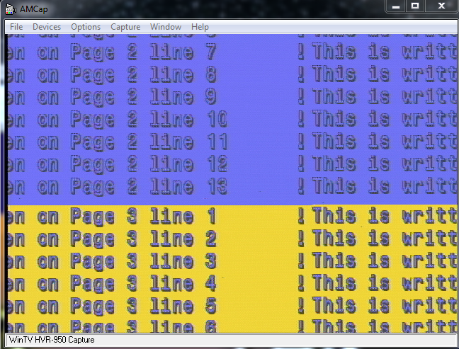
So lets push those 2 bytes up to the offset for line 481 and see what we get: (We will get to the math later)
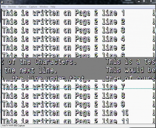
Well.... we have a problem here. We can see that we now start to show what is at line 481. and it continues. But then you see somewhere in the middle there it just completely ends. And when it does end, it seems to show whats back at the very beginning of the memory block its currently looking at. and its totally out of alignment.
Almost looks like an overflow problem, doesn't it? Well lets take a look:
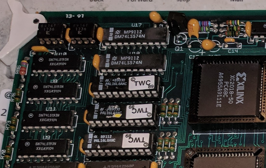
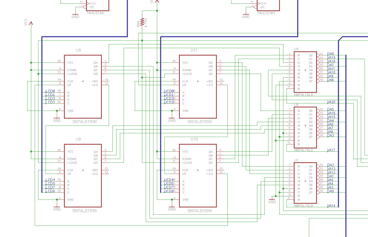
This is a picture clipping of the upper left corner of the graphics card. To the left, you can see a set of 74LS193 ICs. these are 4 bit counters. There are 4 of them... Stands to reason we can make a pretty good assumption that these counters are responsible for what pixels are displayed on the screen, and where... given they are coupled to the PALs, like so:
Notice these chips can count up, down, can be loaded with a value, etc...
With this information, lets do some calculations. We know that each 1 tick of the count value will represent 8 pixels on screen. So. a count value of 65535 or the maximum value of a 16-bit word, represents 8191.875 blocks of 8 pixels. so if we multiply that to get per pixel, thats 524,280 total reachable pixels with that 16-bit value. There are 768 pixels per line.
So... That gives us a window of 682.65625 lines before the counter overflows! And on that screenshot above, That's about where we end up before it "wraps around".
Knowing this, That suddenly triggers the memory of that 3rd byte. That must be the "paging" register for each group of 682 lines.
However there is a caveat. Notice its 682.65625 lines. Well... that means at line 682, somewhere at .65XXX we lose pixel information.
Therefore line 682 is basically lost. And since we need to switch pages using the paging register to see line 683 and higher, We absolutelly cannot draw anything that crosses these "overflow boundaries". So effectively, line 682 is useless. you have to skip over from line 681 to 683 and use 2 viewports on screen at the same time with two different window heights as we discussed above.
This is a pain in the ass, and one of the limitations of the framebuffer. So personally, I skip over this. Anything past line 480 is basically wasted except radar. radar takes 120 full lines, so you can fit it within a 682 line "page"
So with the paging register, we have 4 682 line pages essentially. and you cant display between pages that cross the overflow boundary without two viewports.
With the above information, we can now clarify the 4 byte viewport values:
00 = Pixel Offset Low
00 = Pixel Offset High
00 = Page and Chroma key
F0 = Viewport Window Height / 2
Hey we are getting somewhere.... On to the next one.
Discussions
Become a Hackaday.io Member
Create an account to leave a comment. Already have an account? Log In.