 Christoph Tack
Power distribution board
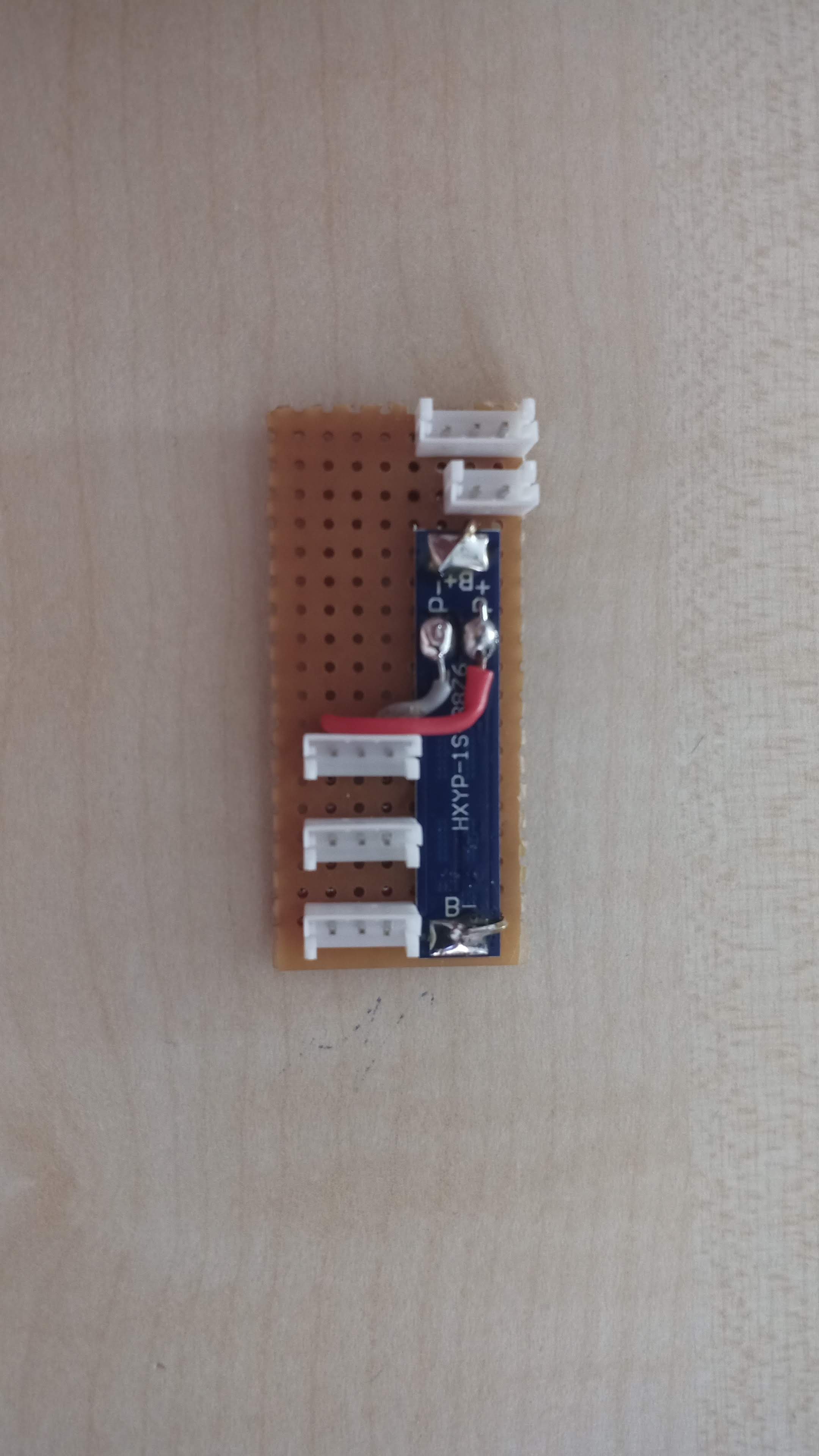
The power from the Li-Ion is connected to the leftmost JST-EH. There's a 2pin JST-EH for the power-interruption switch between the battery and the battery protection board. It might be wiser to connect the battery monitor circuit directly to the battery and then put the power-interruption switch. I'll have to find out later.
The three bottom 3-pin JST-EH connectors connect to the two boost converters and to the ESP32.
Li-Ion protection
A test using 2x 1S/3A-Li-Ion protection from AliExpress (€0.30+€1.15 shipping) showed that it was inadequate. The current limit is too strict.
- UVLO = falling voltage: 2.5V, rising voltage: 2.84V (tested)
- Over voltage lockout = 4.25V (tested). The FET goes into LDO mode, limiting voltage to 3.77V.
A better option would be to order this battery monitor system (BMS) instead.
Motor Power supply
The traction motor will run on 12V, the steering motor on 7V. Two boost converter modules will be used. The quality of those modules is not great. One gave hiccups when the traction motor went full power. Replacing the module was the quickest fix. I bought them as MT3608 boost converter modules. The label on the package is "XT1208".
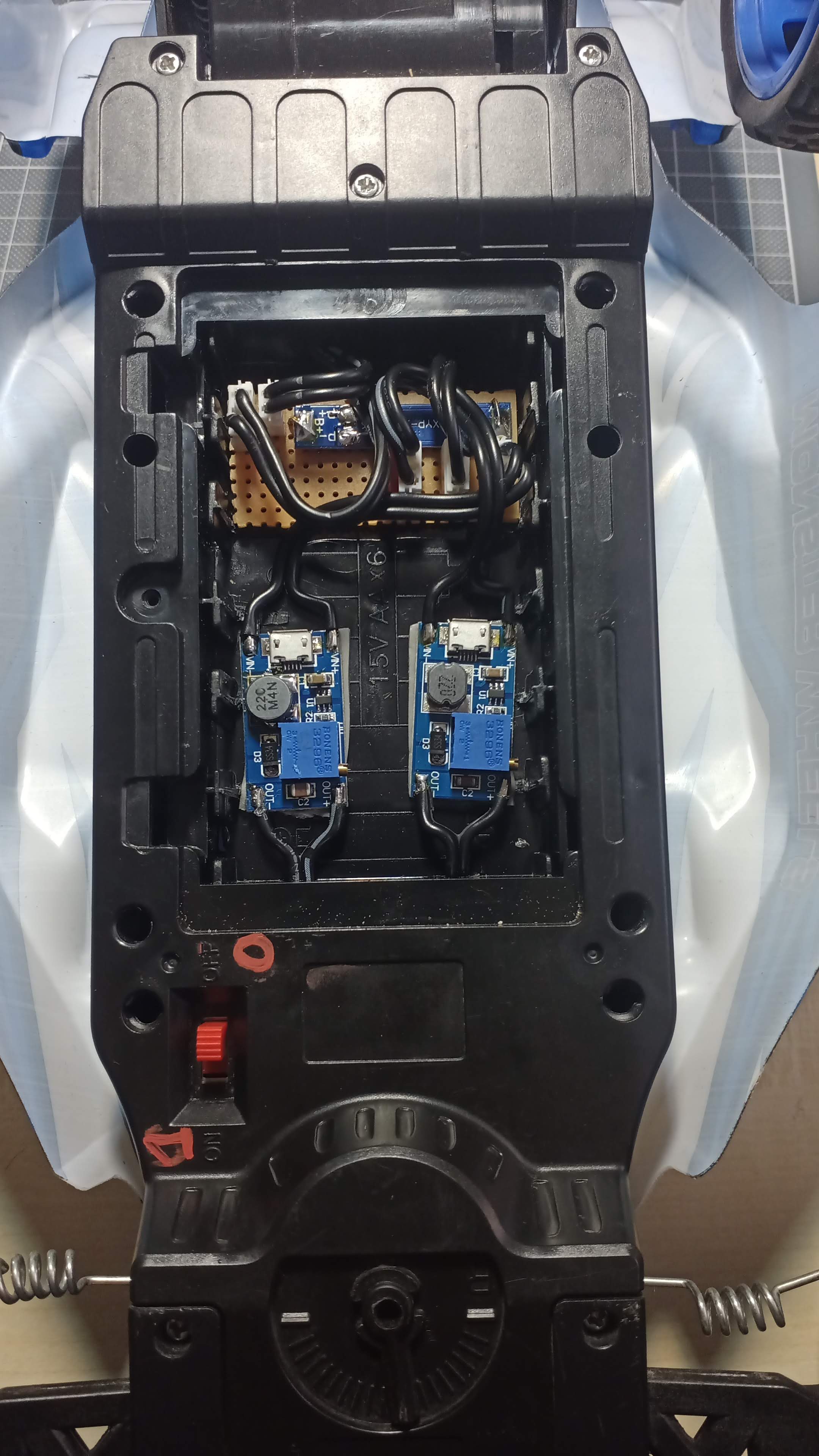
The two boost converter modules are fixed with 3M VHB-tape. It sticks well. It's thick so it can be used on uneven surfaces. It's also easy to remove. It doesn't leave traces of sticky glue (unlike duct tape which is a hell in this regard).
Discussions
Become a Hackaday.io Member
Create an account to leave a comment. Already have an account? Log In.