 Christoph Tack
The ESP32 development board has an AMS1117-3.3 linear regulator. The datasheet announces this regulator as LDO, while the dropout voltage is typically 1.1V! A quiescent current of typically 5mA is neither something to write home about. But that's what is. Don't use this ESP32 board for a low power application.
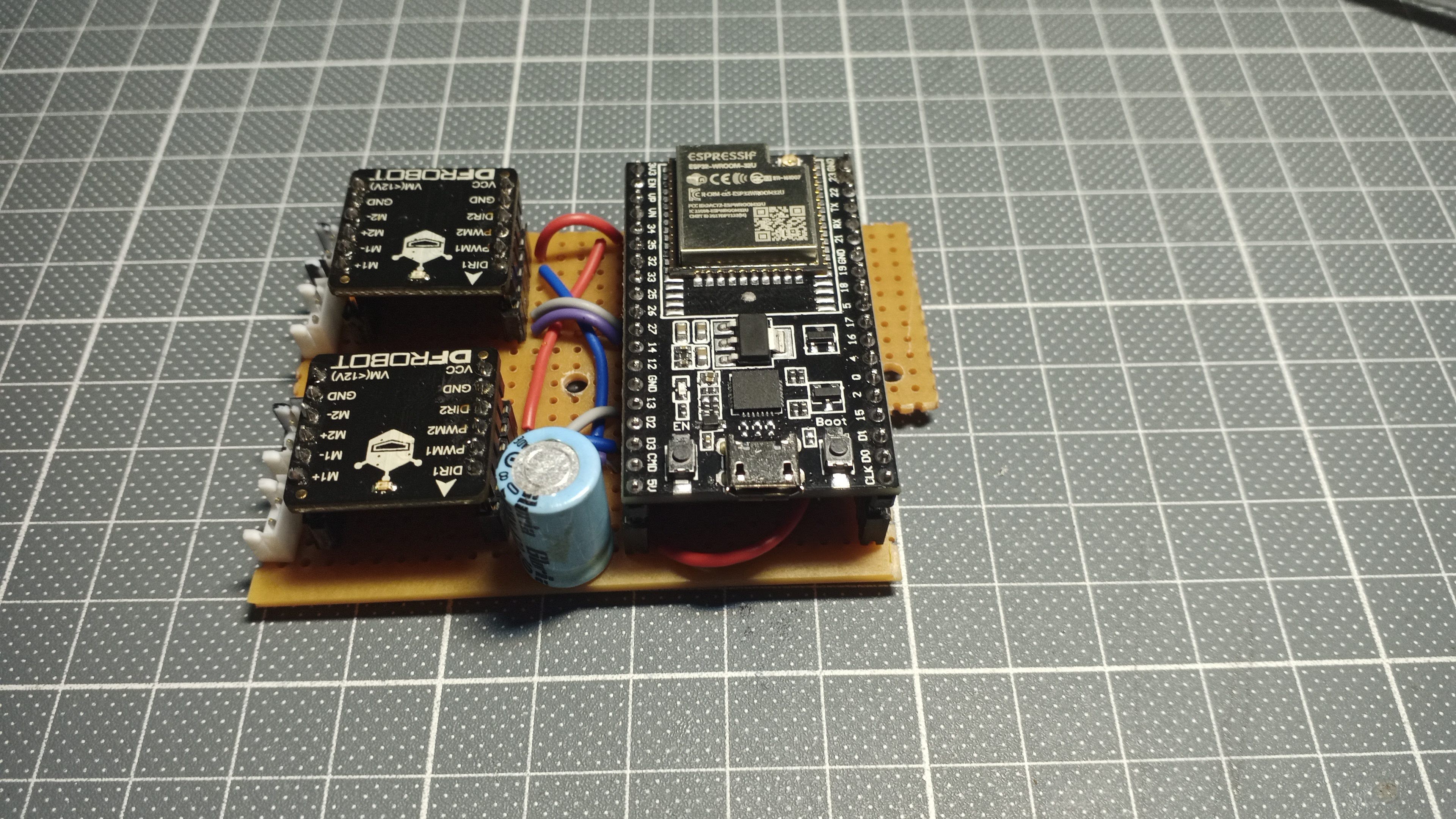
To get a stable 3V3 on the ESP32, the battery voltage must be boosted to 5V (or 5.5V). The same boost converter type that also powers the motor shields will be used here. It's mounted between the ESP32 and the breadboard.
An extra 470µF/10V is added on the 5V input of the ESP32 board. Just in case.
The ESP32 uses two GPIOs to control each DFRobot motor driver. There's a 3pin JST-EH to power the ESP32 with the Li-Ion cell.
The motor controllers are powered by the boost converters (bottom JST-EH on each motor driver). The other JST-EH connector is connected to the DC-motor.
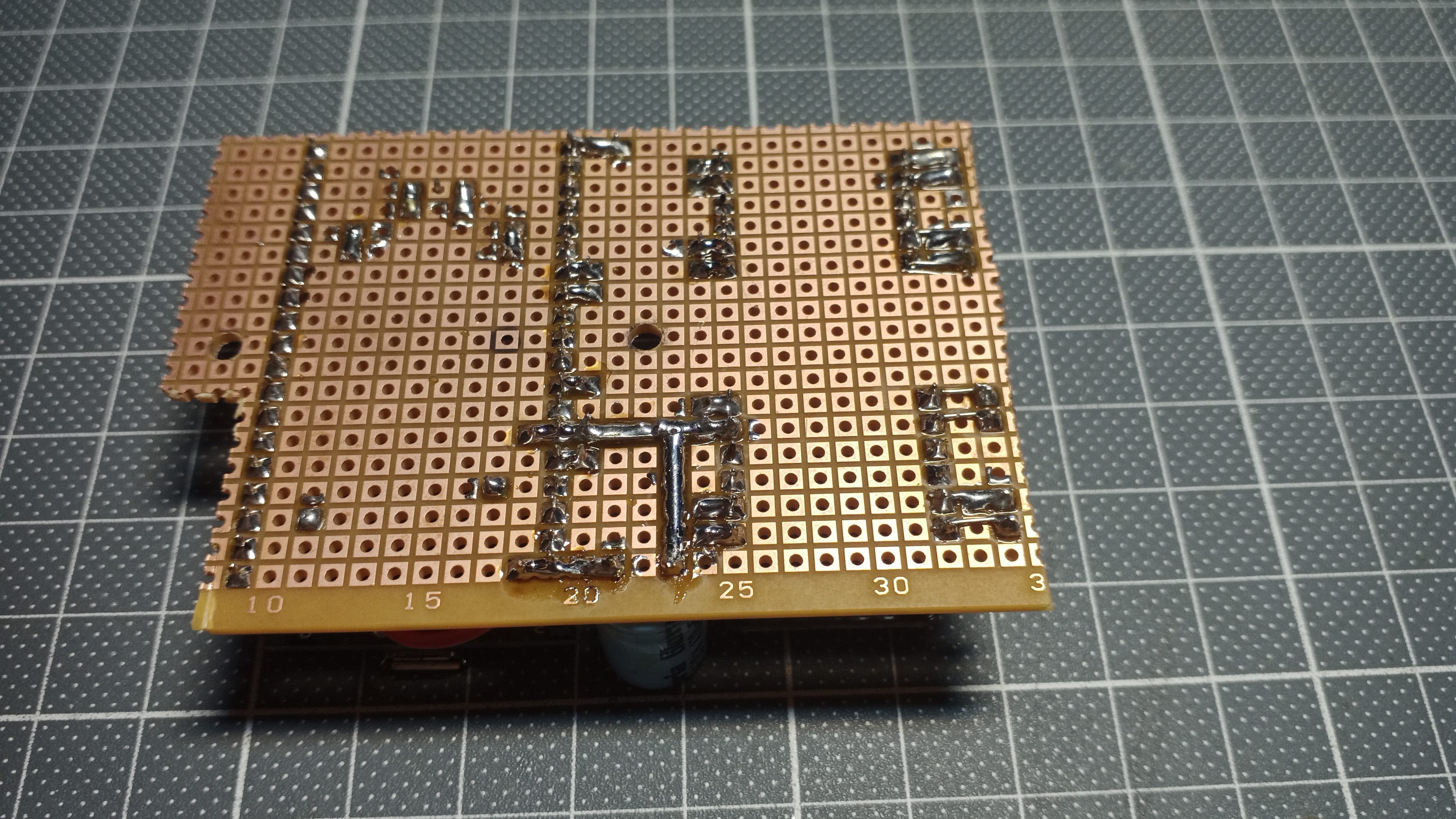
Electric connections to the main body
All connections are made using JST-EH connectors.
There's a 3-pin connector for powering the ESP32.
There are two pairs of 2-pin connectors for powering the motor controllers. The remaining two pairs with red/black wire are connected to the two motors themselves.
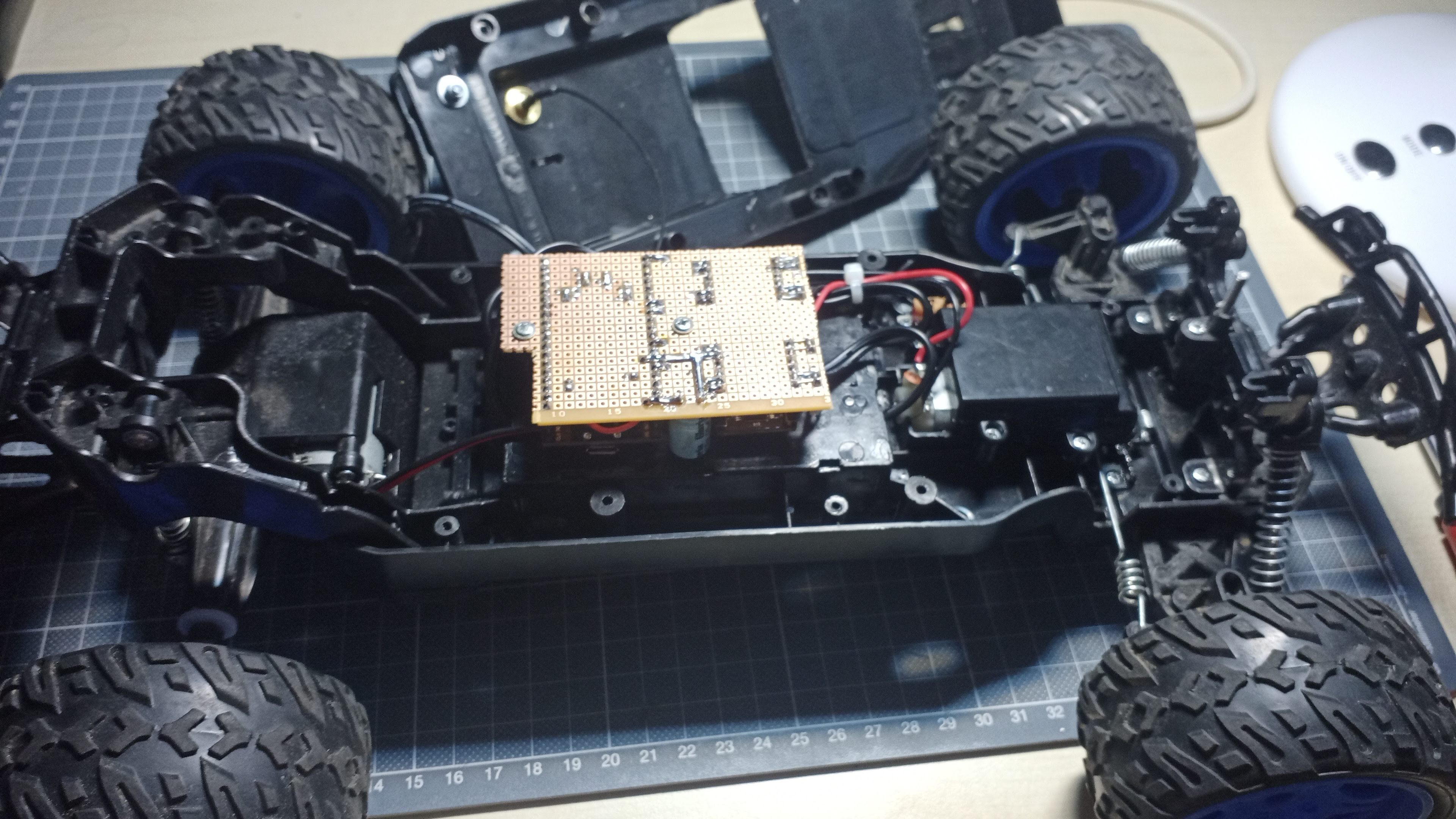
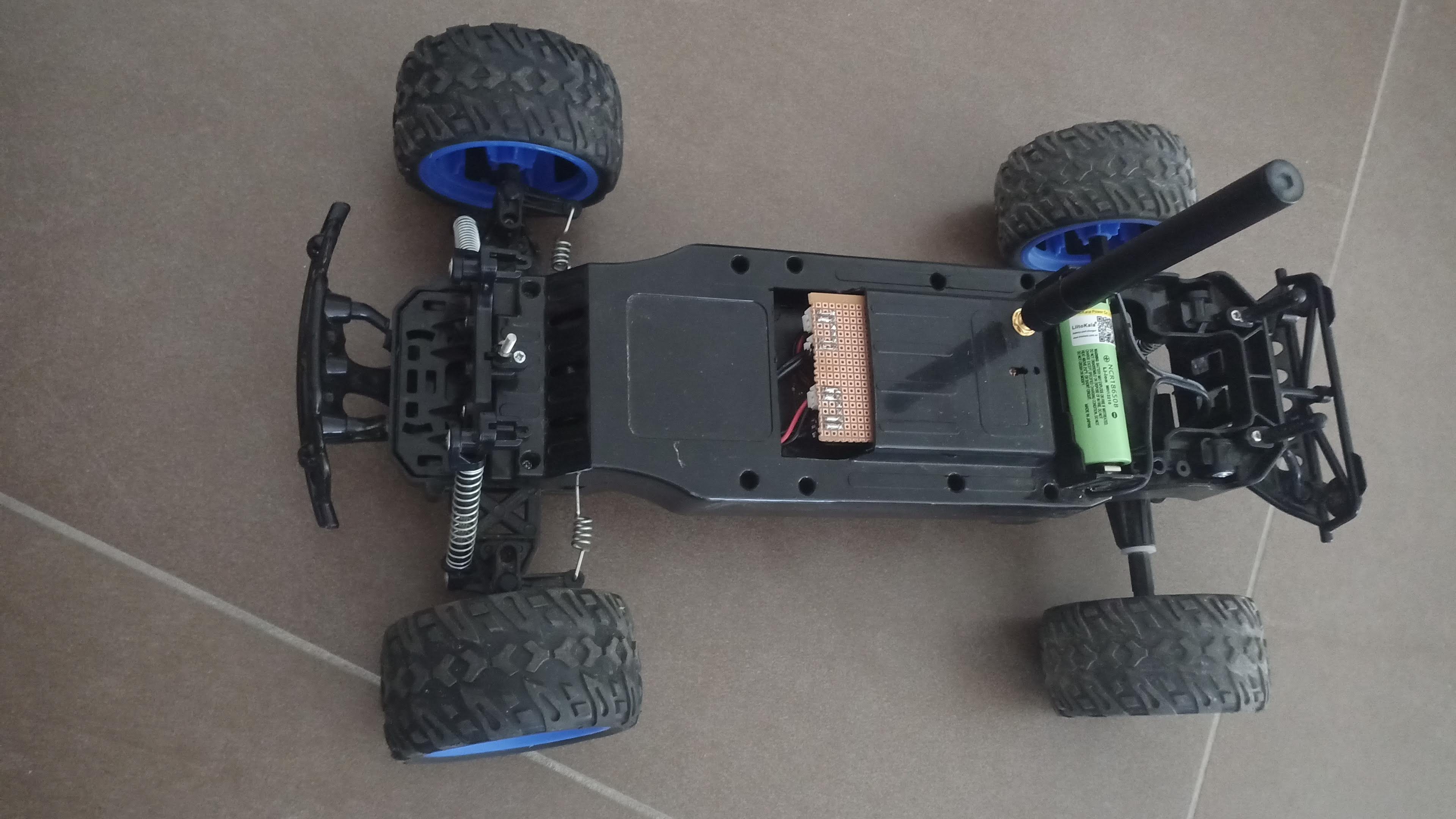
Controller PCB mounted
In the background, the shell is visible with the antenna mounted in it.
Shell closed
The controller board requires more space than the original electronics. Using a Dremel tool, I made a cutout in the shell. The cutout is too big, but at least the circuitry fits easily.
The 18650 battery clip is also mounted onto the shell, as well as an RP-SMA antenna pigtail cable for the LSR antenna.
Discussions
Become a Hackaday.io Member
Create an account to leave a comment. Already have an account? Log In.