 iSax
iSaxMicro controller and logging
The readily available and cost effective Arduino UNO was used as the logging device micro controller. However using only the Arduino and exernal sensors poses two problems. Firstly the internal EEPROM is only 1024 bytes. This is not enough to store the data generated by a frequent and long lasting measurement setup. The second issue is keeping time. The Arduino starts an internal timer when it's powered on and this timer counts as long as the power is not lost. With frequent power outages and risk of the device being unplugged it would be impossible to know when in time the charge events would happen after loosing power the first time.
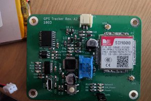
The two issues presented above are solved by one shield, an add on board that easily connects to the Arduino. The shield features a SD card reader/writer and a real time clock. The SD card installed is 4GB and gives space for more than two years of measurements with a one second interval. The RTC, once set one time, keeps the time even when no external power is available with it's own back up battery. When the logger is restarted the new measurements will be saved with a correct time stamp.
Sensors
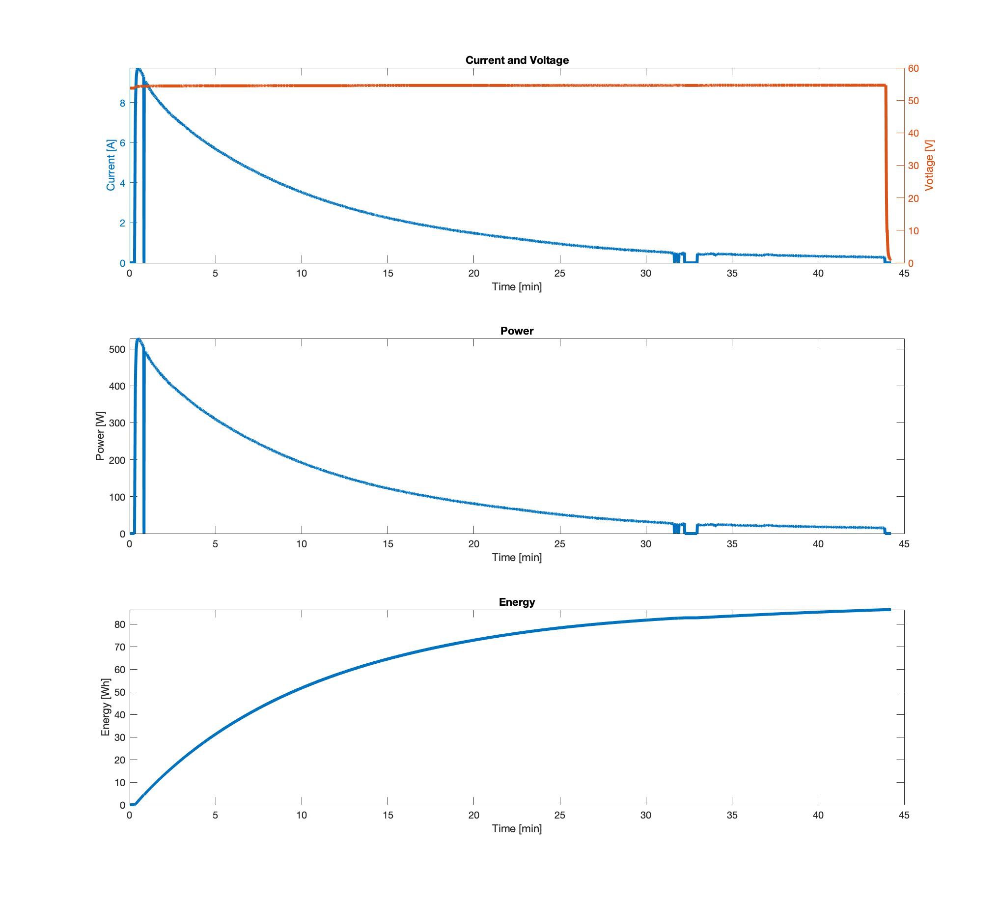
The code will create a comma separated value (CSV) file on the SD card for each power on and start logging voltage and power. To reduce noise the system will make 15 measurements with the analog inputs every second. These 15 values are then averaged and only the average value are saved one time per second.
\subsection{Sensors}
For measuring the charger currents up to 10A the ACS712 chip was used. It's supplied in handy modules in 5A, 20A and 30A ranges. I used the 20A. This uses a hall effect sensor and no current shunt resistor is needed. The high voltages around 50V can not be fed straight into the analog inputs of the micro controller but a 240k voltage divider with a reduction ratio of 12 was used. The total power draw of the divider is 15mW. With these two low cost and simple probes an error of less than 5% can be reached which is enough for the needs. The data logger can be seen in figure.
 Bertrand Lemasle
 Jan Waclawek