0%
0%
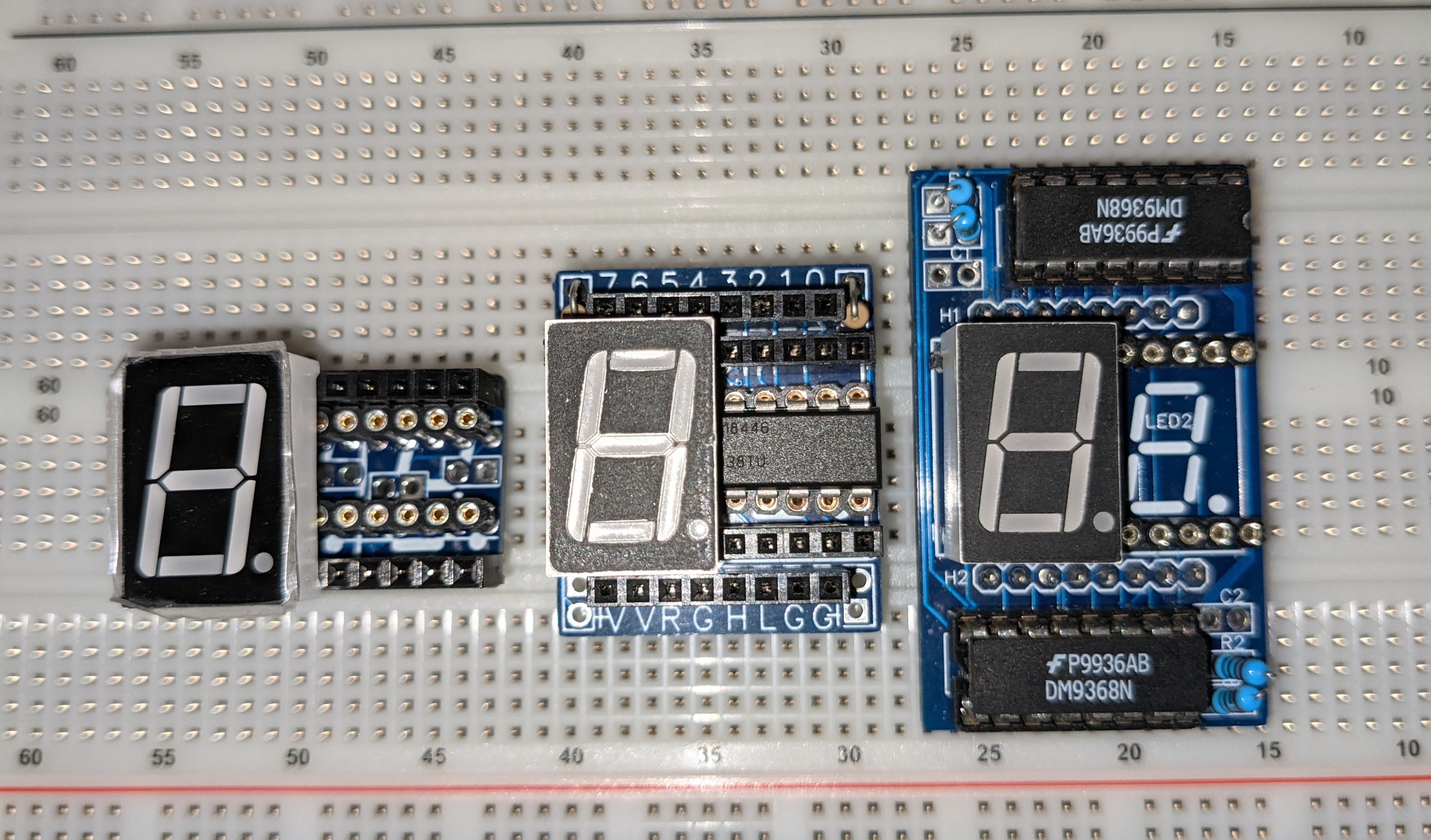
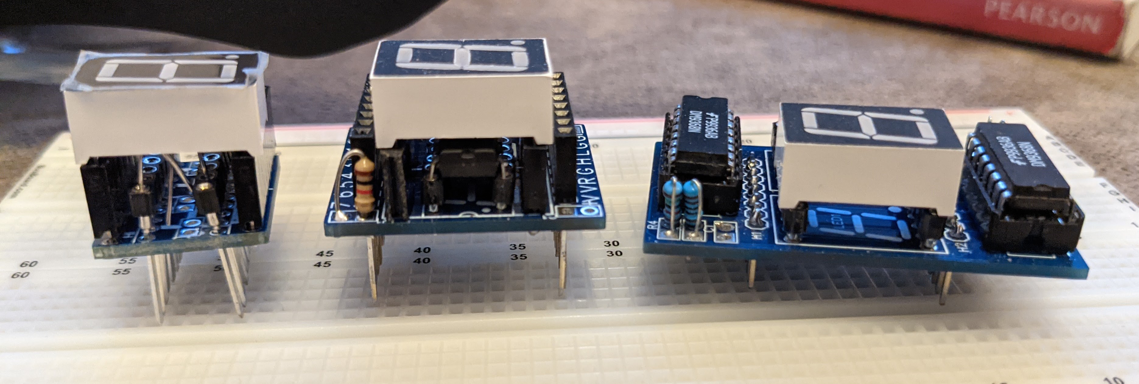
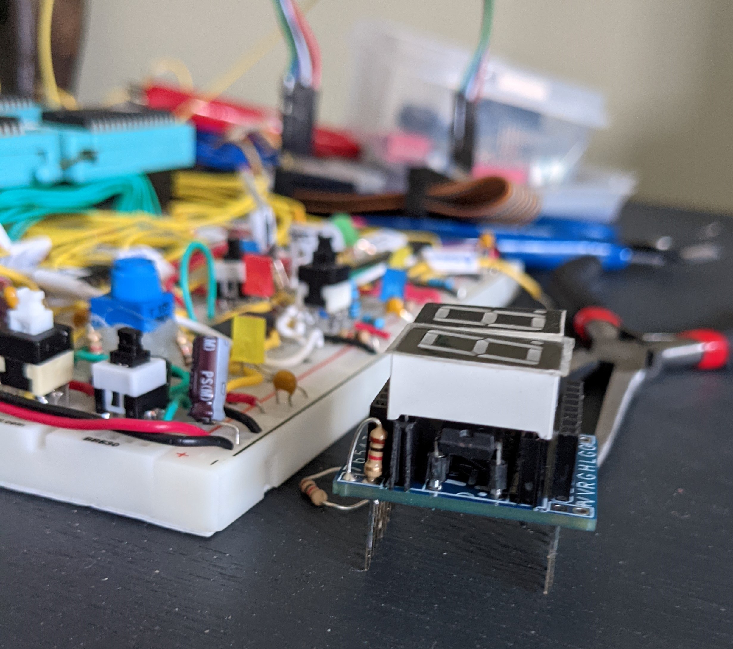
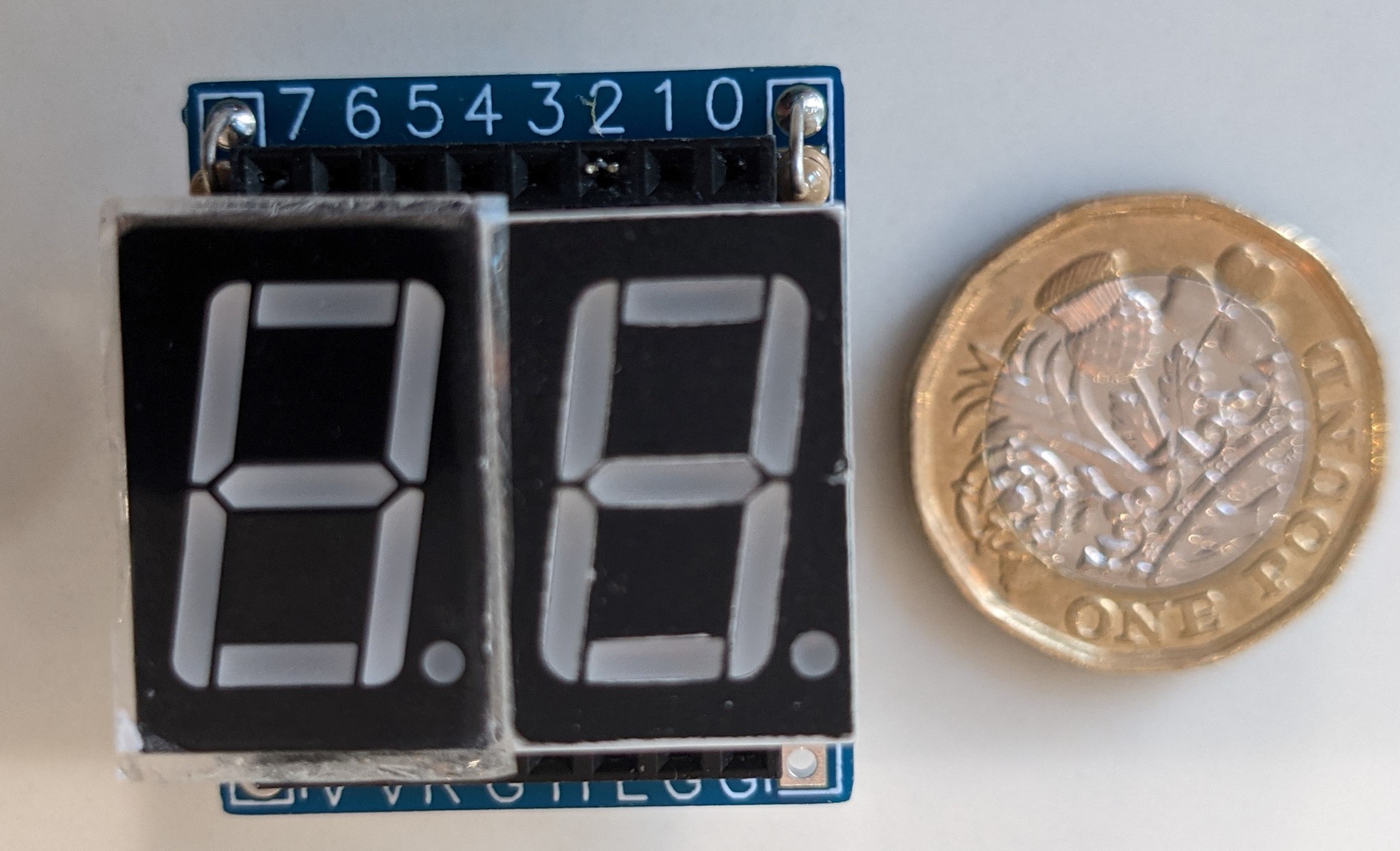
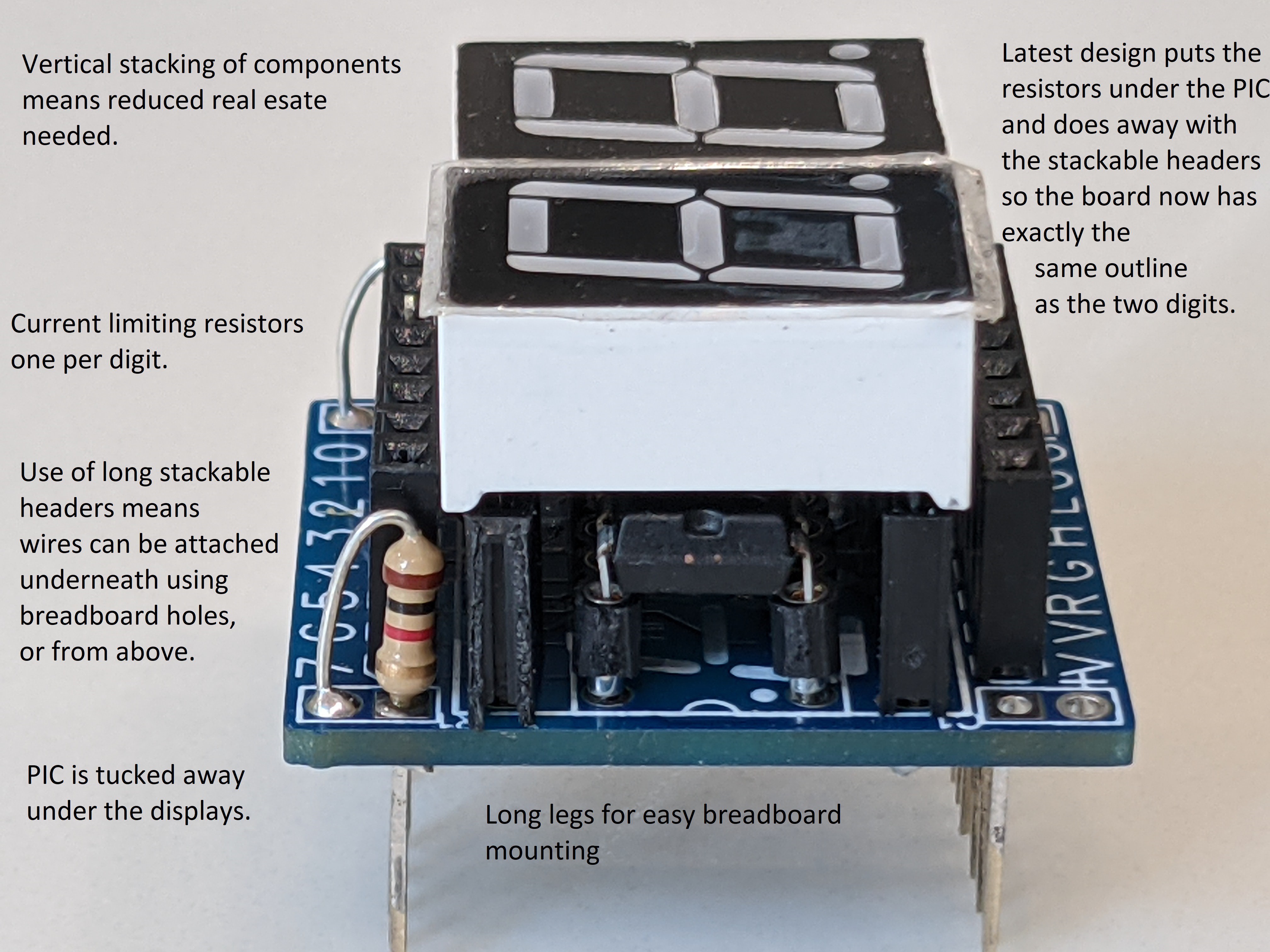
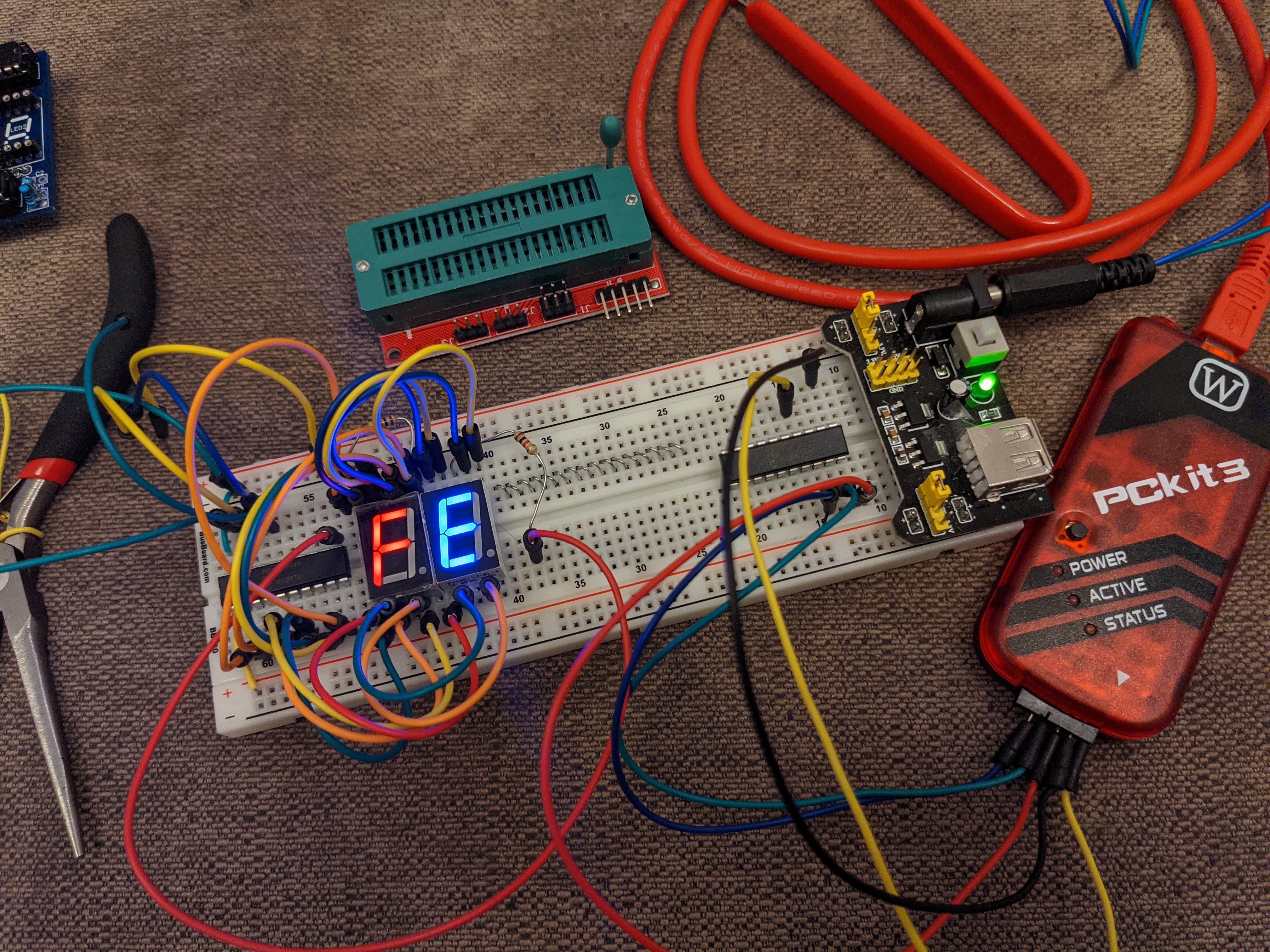
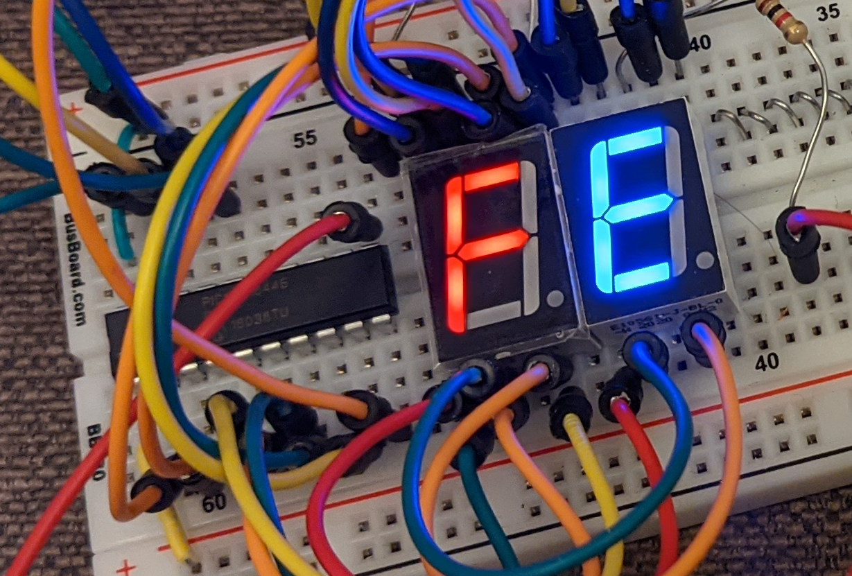
Dual 7 Segment Hex Display Module
Two digit (8 bit) hex display using a PIC16F18446 microcontroller
 John Lonergan
Become a Hackaday.io member
Already have an account? Log in.
Just one more thing
To make the experience fit your profile, pick a username and tell us what interests you.
Pick an awesome username
hackaday.io/
Your profile's URL: hackaday.io/username. Max 25 alphanumeric characters.
Pick a few interests
Projects that share your interests
People that share your interests


 Ken Yap
 Anders Nielsen
 deʃhipu
 OzQube
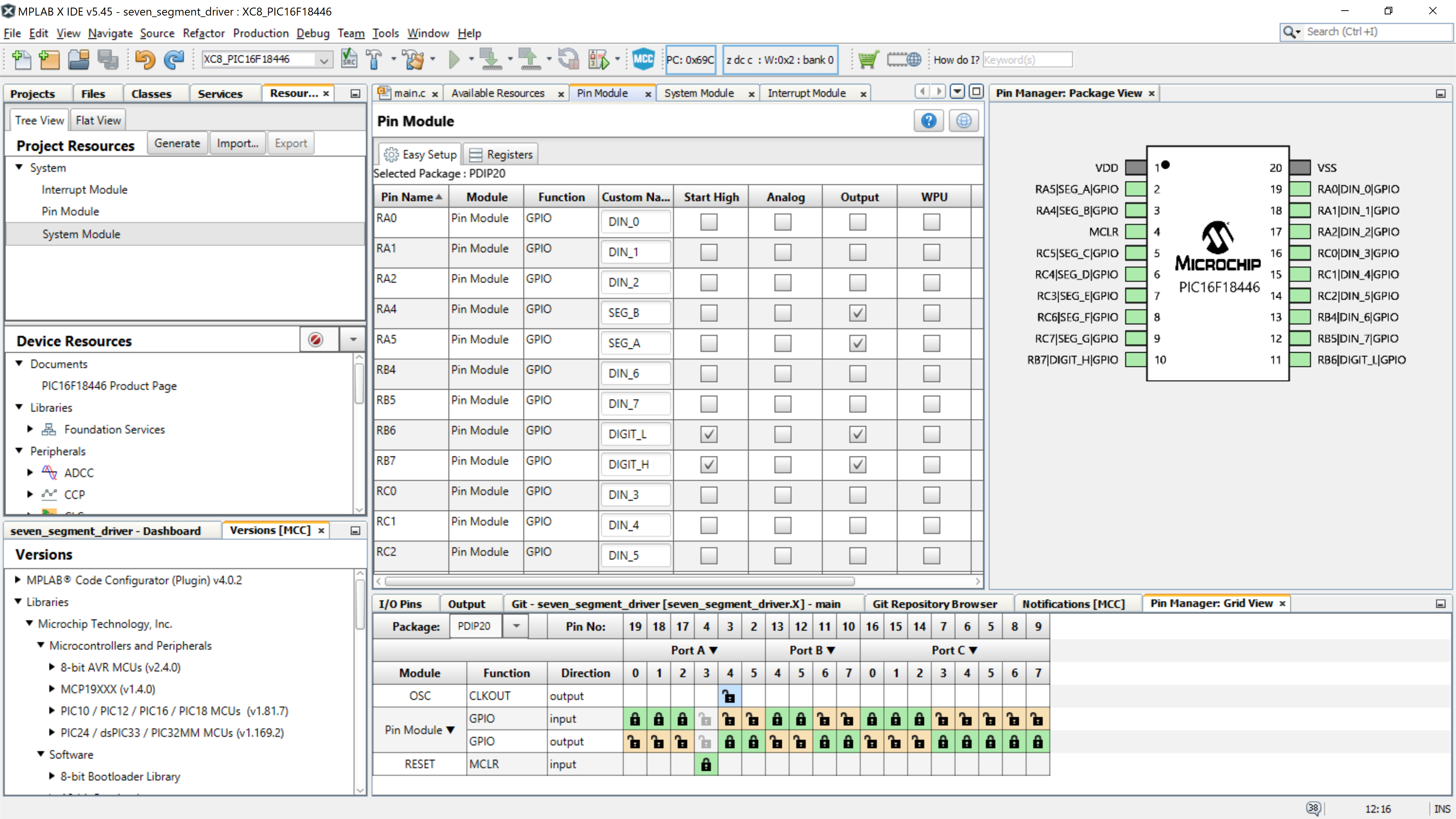
I thnk there's a free less capable version of the IDE and compiler (installed separately) but it can be confusing to work out what can be used without a license.
You can also use SDCC to compile for PIC, see the end of my page here: https://hackaday.io/page/7182-hacking-on-teds-led-clock-software Hopefully that PIC model is supported. But I only generated the code and don't actually have any PICs to download to so you would have to figure out how to do that without the MPLab IDE. Often I find working with the CLI and Makefiles more straightforward than a huge IDE. But I think MPLab has simulation and debugging support. And lots of hand holding while developing.