 John Lonergan
TL;DR buy a cheap PicKit3 and use it to program your PIC via a breadboard
Things I learned ...
DO NOT try a TL866II programmer.
Somehow when I ordered these devices I had the idea I could program them in the TL866. .But that didn't stop me trying. The TL866 does support some PIC16's so I selected one from the config and put in my own PIC and tried programming. No joy. Given that te pinout was completely different this isn't surprising.
I then recalled that the TL866II has an ICSP port that might be used to program things like the PIC.
DO NOT try to use the TL866II ICSP port either
There's no point trying to use the ICSP port if the programmer doesn't undertand what the PIC16F18446 is. Apparently each family of PIC can have a different programming protocol on the ICSP lines so really wiring it up isn't enough. Perhaps they will add the PIC16F18446 to the TL866 in future. But for not it's hopeless.
At this point I figured that I have killed the two PIC's I'd been experimenting with.
Over on the EEVBlog someone told me to save misery and invest in a PIC programmer. On AliEpress (or via Ebay) it's possible to get a PicKit3 for £7 but I didn't want to wait a month for delivery. Instead I found one for three times the price but with next day delivery.
DO USE a PikKit3 programmer
With my new PicKit3 in I got no instructions but it did come with a board carrying a ZIF socket.
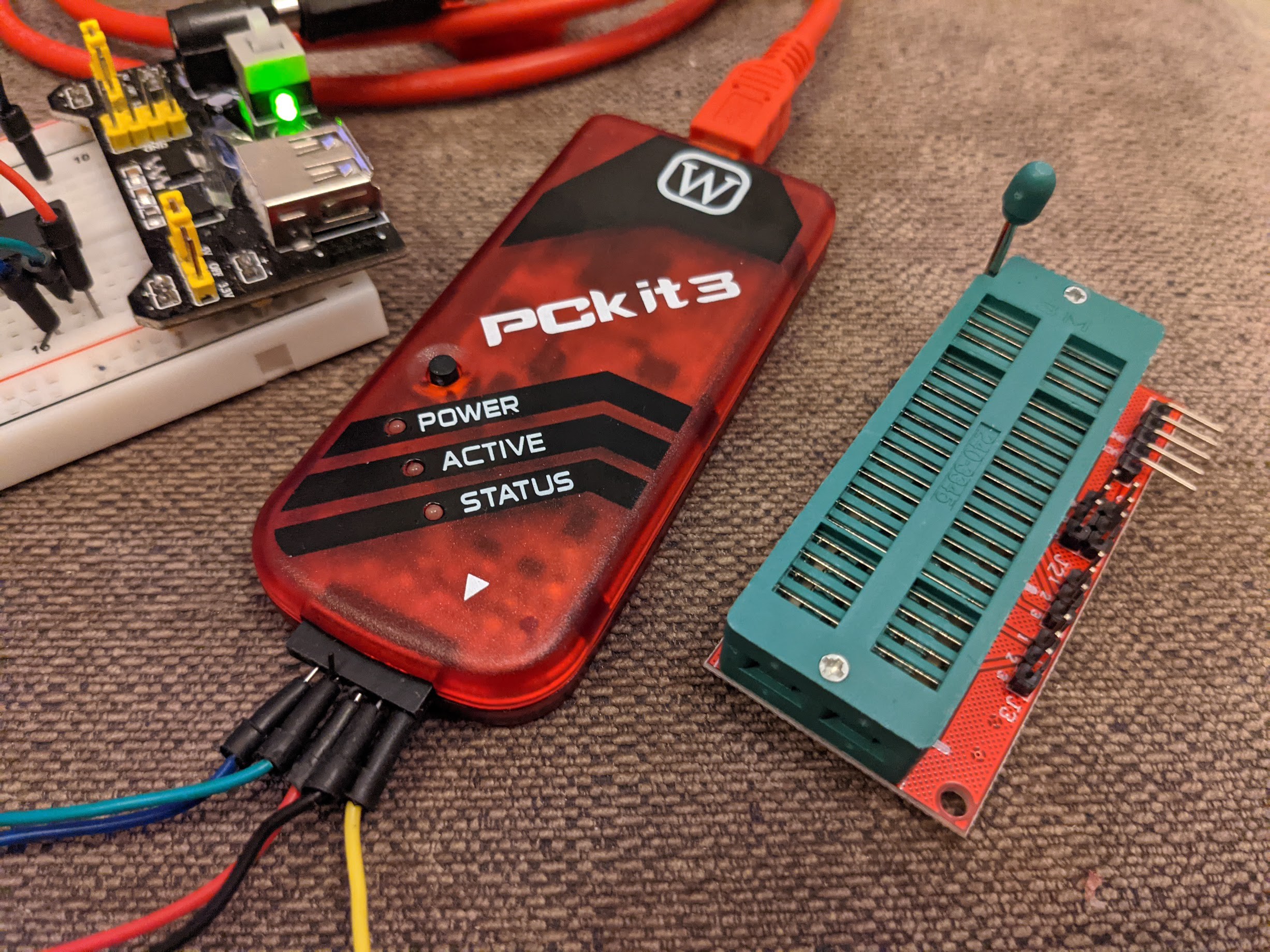
I found that on the bottom there was a stencil that indicate where to place the chip in the ZIF.
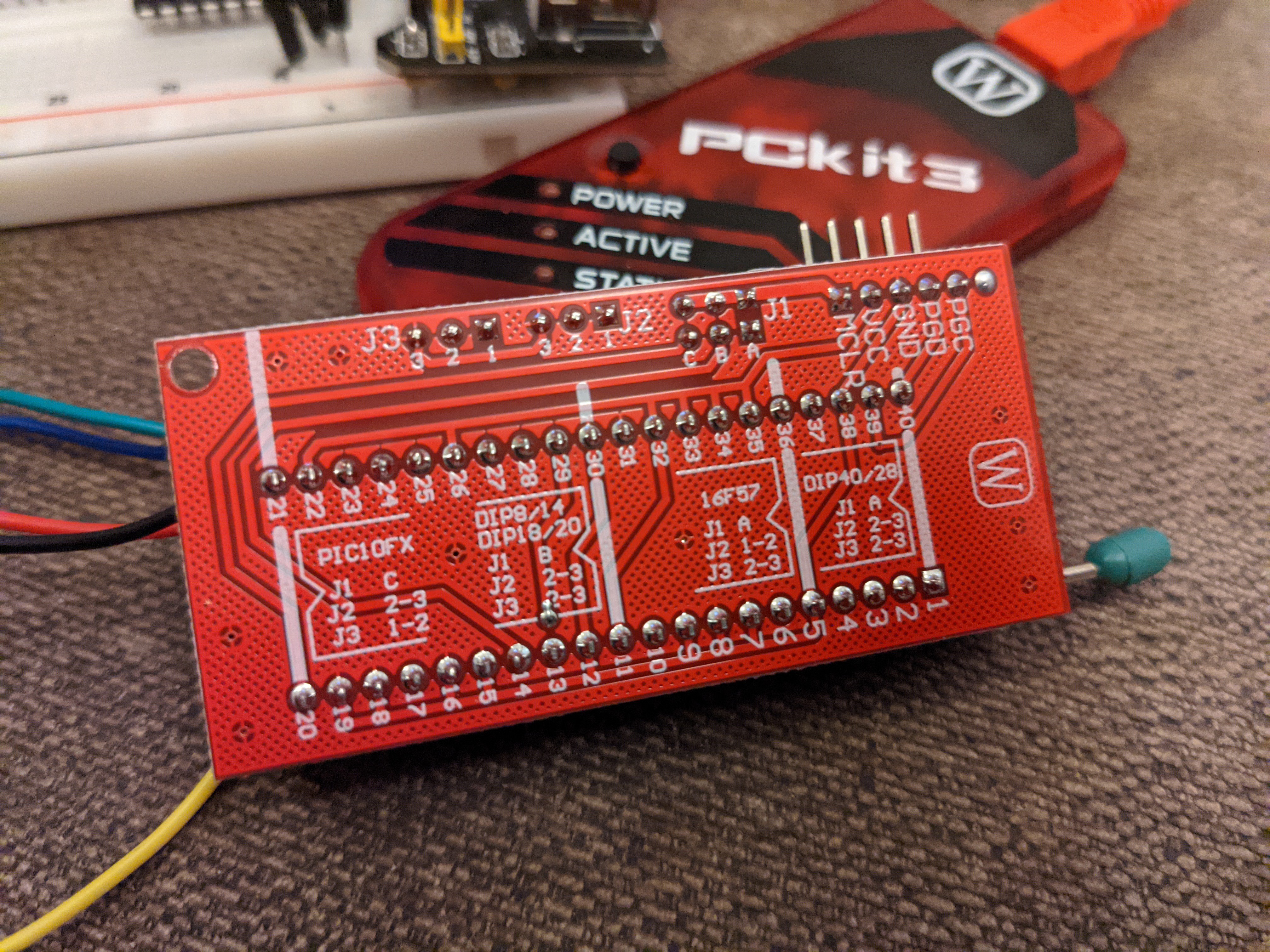
DO NOT use the PicKit3 ZIF board!!
So again hoping for the best I put a PIC into the socket where it indicated a 16F device and tried programming.
What I found was that the PIC got extremely hot!
It got so hot that the ZIF socket got quite warm and I was also worried that I'd probably killed the programmer device.
Another dead PIC probably.
I realised that to use the PicKit3 ZIF board I'd need some doco, so I gave up with it and decided instead to wire up the ISCP port pins of the PicKit3 to the PIC chip via a breadboard.
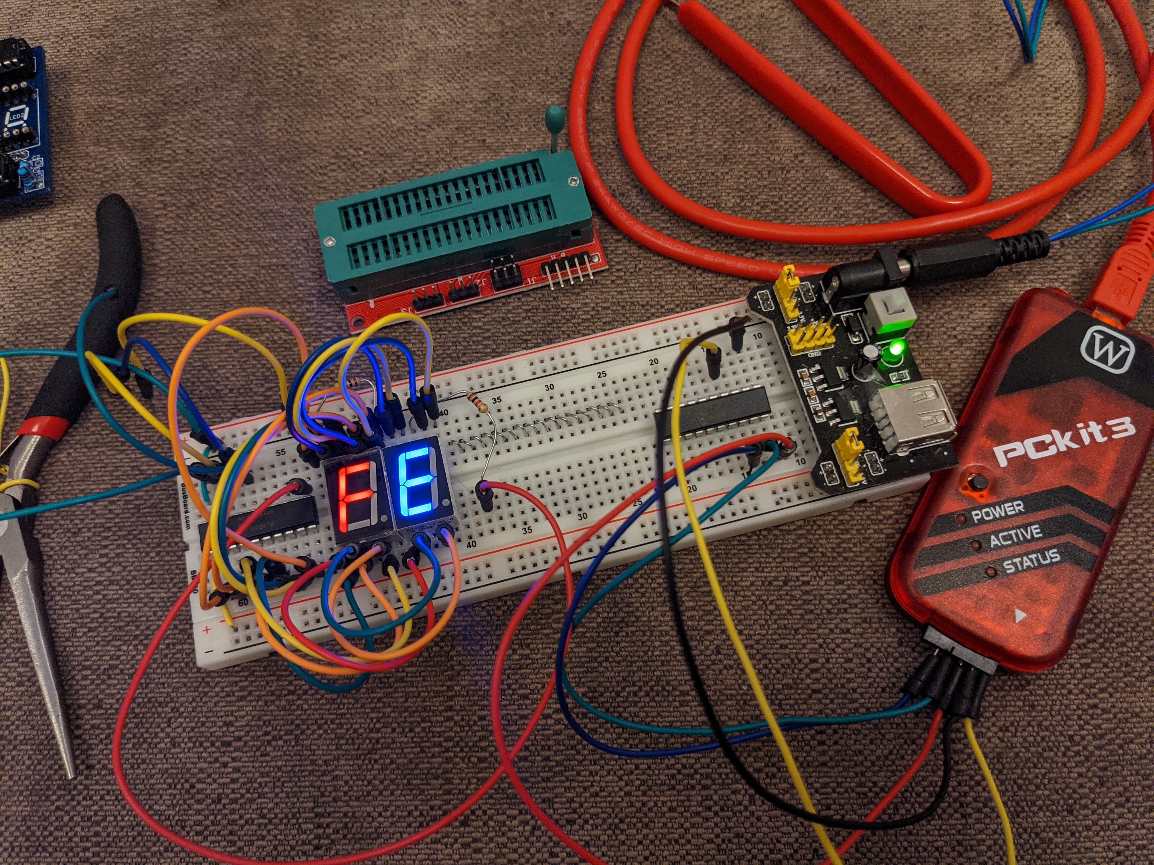
DO wire the PIcKit3 up to a breadboard.
With the five ICSP wires of the programmer hooked up to the PIC16F18446 the Mocrochip programer sofware was finally able to recognise the PIC device.
DO USE the MPLAB IPE to program your PIC16F18446.
The Hex file was created by the MPLAB IDE using (I will upload the project) but to program the hex file into the PIC you need to use the MPLAB IPE (integrated programming env) which is simply the Microchip provided control software for programming PIC's via various hardware interfaces. My hardware interface was the PicKit3 and the IPE was able to immediately recognise the PicKt3.
To program the PIC I turned on the option for the PicKit3 to provided power tio the PIC. Note: In the image below you can see a breadboard PSU on the right end of the breadboard howevert this is wired up to the LED on the left and plays no part in the PIC programming.
IF NECESSARY turn down the supply voltage
I got a warning about the PicKit3 not being able to supply 5v to the PIC but since the PIC will run at much lower voltages I went into the options on the IPE and turned the voltage down to 4v. With this change I was able to program the device successfully in a few seconds each time.
In the IPE loaded up the hex file produced by the build of my project and then hit the program button.
PAY ATTENTION to the supply pins
I burned out one chip by putting the supply the wrong way. The GND is pin 20 where 5v would be on a TTL chip. The 5v supply is on pin 1
---
Success.
Discussions
Become a Hackaday.io Member
Create an account to leave a comment. Already have an account? Log In.