 dekutree64
Arm segment lengths: Both 135mm
Shoulder range: -40 to +125 degrees
Elbow range: 0 to 159 degrees
Angle 0 points toward positive X. Positive angles turn counterclockwise. If shoulder angle and elbow angle are 90, then the shoulder axis, elbow axis, and nozzle all lie on the Y axis (centerline of the bed).
Arm uses GT2 timing belts and pulleys. Shoulder reduction is 7.5:1, elbow is 5.625:1.
Shoulder: Single stage, pulleys 16:120, belt 280mm, center distance 63.10mm
Elbow motor to second stage: Pulleys 16:60, belt 200mm, center distance 60.37mm
Second stage to elbow: Pulleys 40:60, belt 400mm, center distance without idler 149.86mm, with 65T idler 135mm
The bed is rotated 25 degrees around the vertical axis to allow the printer to be very low-profile while having room for the elbow to not run into the wall. Can be a bit confusing since there are essentially two coordinate systems being used in the physical design; one relative to the wall and one relative to the bed. Though from the software side, the bed coordinate system is all that matters.
Bed dimensions are nominally 300x200mm, though the arm can't quite reach the two outer corners. The unreachable areas are approximately triangular, 50mmx25mm on a 300x200mm bed, or 50x50mm on a 350x200mm bed. The bed width can be up to 450mm, though anything over 300mm has an unusable area at the bottom left corner because the end of the arm runs into the wall. Also noteworthy is that the printer can be self-replicating if you use a 300x215mm bed. The extra length isn't that useful most of the time since it can only be reached near the middle, but BedTop.stl can't be printed without it.
The near edge of the bed should typically be 50mm from the shoulder axis center (the minimum reachable radius for the arm)
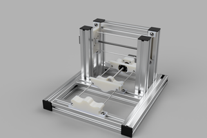
The printer is designed for Creality style hotend and extruder and 4010 fan. It has an integrated mount for Petsfang Bullseye part cooling duct (https://www.thingiverse.com/thing:2759439), which takes a 4010 centrifugal blower. If you want to use a different hotend, the end of the arm can be modified as necessary to mount it. If possible, keep the nozzle in the same place. Otherwise the effective arm length and/or max elbow angle will be changed.
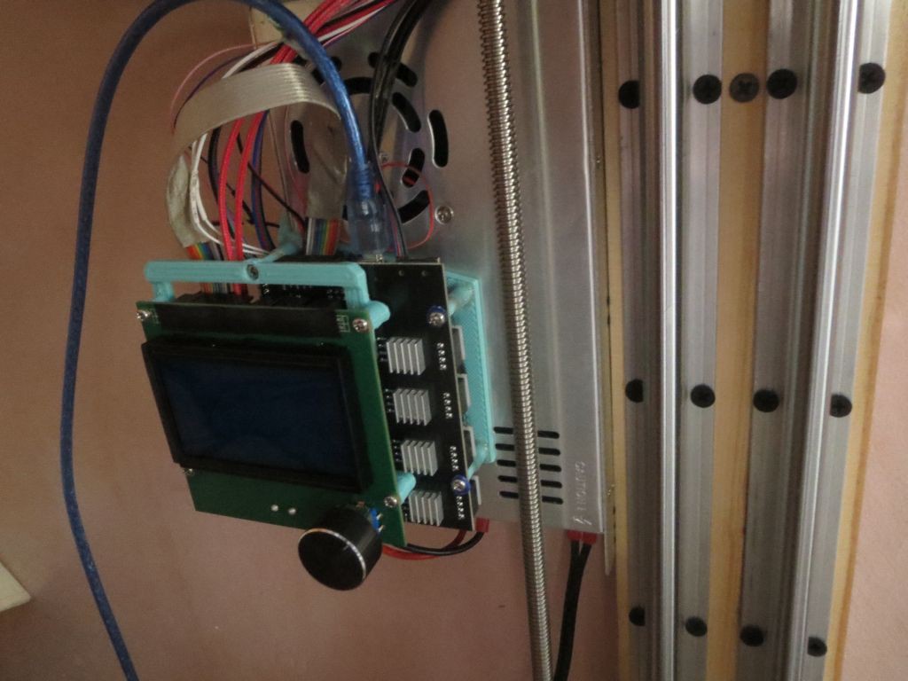
The arm uses sensorless homing, and Z axis uses an optical endstop.
I took some measurements to see how much everything deflects with weight on the bed.
Leadscrew deflection: Rail carriage drops 0.1mm per kg of mass placed on the bed.
Bed deflection: Center of bed drops 0.3mm per kg of mass evenly distributed on the bed. Subtracting carriage deflection, this is 0.2mm due to combined bed support spring compression and tilting of the bed (rotating around the hinge). This works out to a maximum of .115 degrees of tilt per kg.

 heinz
heinz
 ahorn42
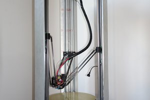
 Myles Eftos
Can you provide more details would love to do a 2020 extrusion variant