dekutree64
-
Not dead
04/21/2021 at 08:04 • 0 commentsFor what it's worth, I have still been working on this intermittently, but still not finished.
I bought some 0.9 degree steppers, which improved the ripples even further.
Calibration gave me a hard time, but I've got it all worked out now so you just take 3 measurements with calipers (shoulder to elbow distance, elbow to nozzle distance, and shoulder to nozzle distance while in home position) and type them into the firmware configuration.
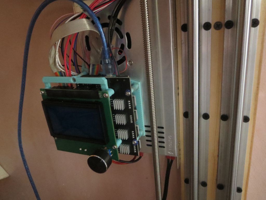
I added an LCD controller. I had originally planned to run tethered to the computer because I was too cheap to buy one, but it really is nice to have, and can still run tethered too.
![]()
I learned a nice new technique from Dan Royer's youtube channel, called crush ribs. Basically instead of trying to make round holes that perfectly match the diameter of bearings, you make them oversize but with a few protrusions that actually make contact with the bearing. It allows things to flex a bit to compensate for the low precision of 3D printing, and works much better than the horizontal ridges used in the Blender model I posted before (which do help, but still often require a lot of fiddling to get a good fit).
But there's one insurmountable design problem, which is that the elbow belt tension flexes the arm enough that the shoulder and elbow axes are significantly out of parallel. The reason I made the arm fairly thick in the Z direction was precisely to prevent this problem, but it seems plastic is just too flexible. I got my printer working by trial-and-error shifting the bearing hole positions by a small amount until the axes are reasonably parallel under tension, but it's not a good solution. Even after a lot of effort it's not as precise as I'd like. I've thought of several options to deal with it, but I don't especially like any of them:
1. Add an adjustable counterbalance tension device toward the bottom of the arm (e.g. a threaded rod or a length of heavy fishing line or thin steel cable), so after tensioning the belt, you can adjust a screw until the axes are parallel.
2. Make one of the shoulder or elbow bearings movable so you can trial-and-error it more easily than what I did.
3. Build in a tilt to the axes, and use the belt tension itself to fine-tune them parallel.
4. Major redesign so the elbow pulley is down in the middle of the arm instead of cantilevered on top, so the tension is supported on both sides.
5. Use a different elbow gearing mechanism that doesn't put tension on the arm in the first place.
1-3 don't address the problem of belt tension varying with force from the motor, but at least with my current acceleration rates it doesn't seem to be a problem anyway. I don't have any ideas on how to accomplish 4, so I think I'll give 5 a try first, using a round NEMA14 motor mounted on the elbow joint with either a compound planetary or harmonic reducer integrated into the elbow.
-
Goodbye pancake
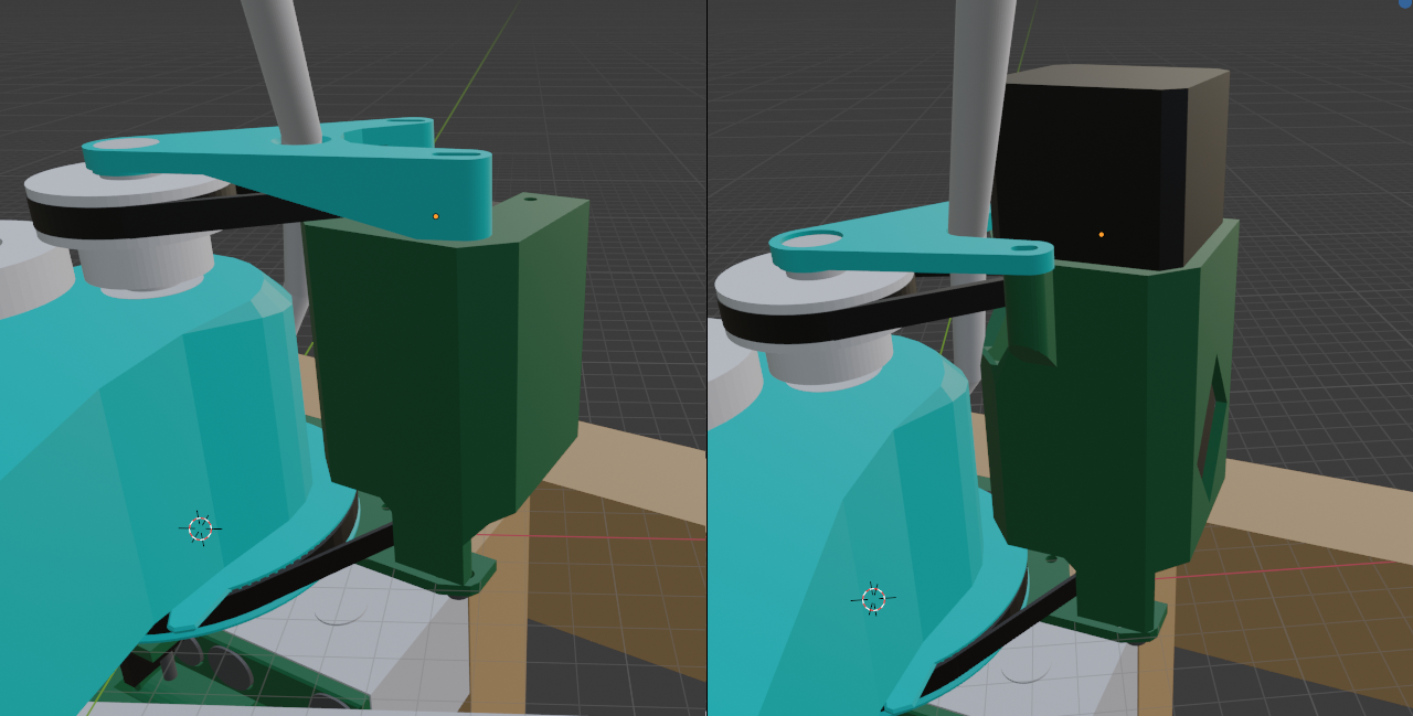
03/18/2021 at 11:43 • 0 commentsAha, so the elbow pancake stepper was the cause of my print quality issues. Apparently it doesn't hold microstep positions as well as the larger ones, causing major ringing artifacts as the arm is able to vibrate between the two full step positions. I tried increasing the current, but it didn't seem to have any effect.
I redesigned the motor tower to hold a second 34mm up on top, which is not quite as elegant as the old design, but actually a bit nicer functionally because it provides a place to trap the bowden tube/wires without having to pass through a hole in the top bracket (which is a major pain if you ever need to pull them back out). I also added a window to improve cooling (diamond shaped to allow printing without supports).
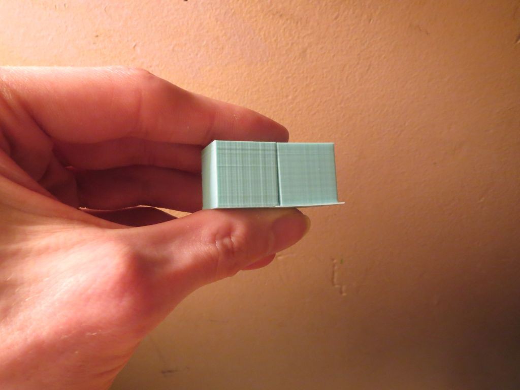
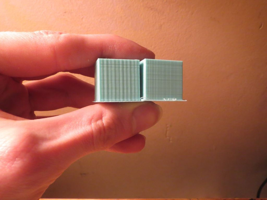
The photos show before and after of 20mm/s and 60mm/s print speeds. Ripples are much smaller now, especially at high speed.
![]()
![]()
![]()