Andrew Lamchenko
Hello everyone! I want to share with you my new open source project. From the title of the article, it is clear that we are talking about a temperature and humidity sensor with a display on electronic ink. For a long time already I tried to make a project of a temperature sensor with such displays in the form of an arduino module. Since then, the topic of e-ink displays has interested me.
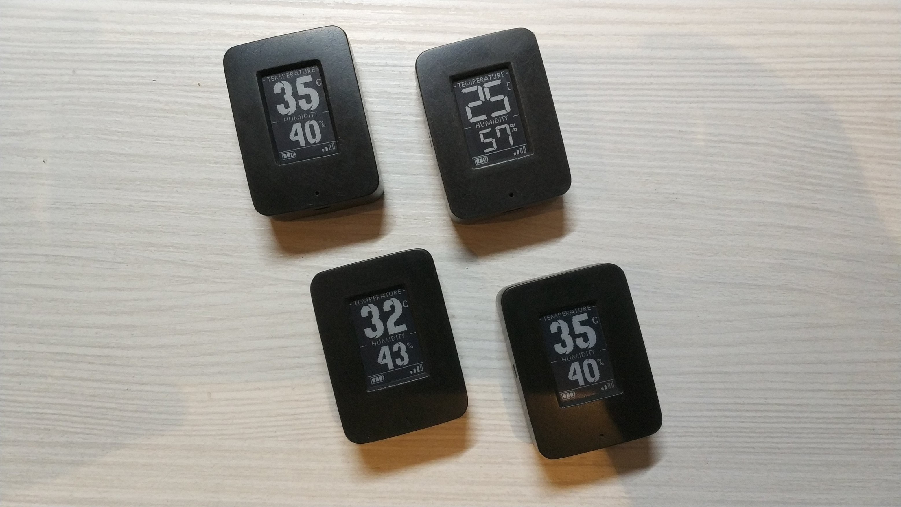
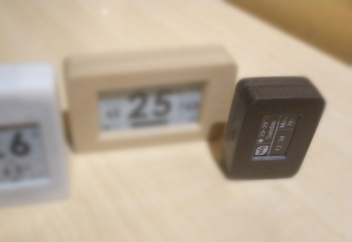
The goal of this project was to develop a miniature sensor, comparable in size to conventional wireless temperature sensors, but at the same time displaying data on the screen of the device itself. And under all these conditions, the device had to work on a small battery for a long time. What came of it, rate, please, and do not skimp on comments.
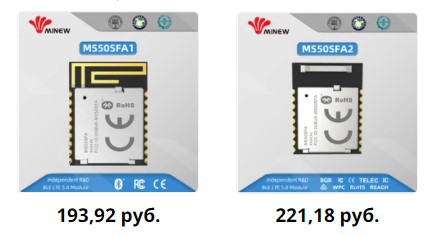
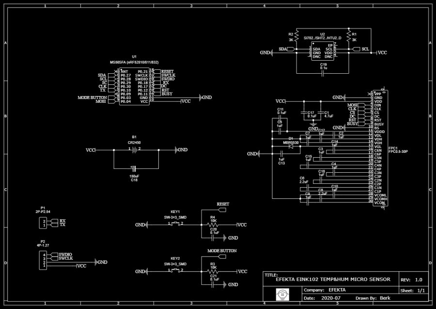
The sensor works on nRF52 microcircuits, for this project a module from MINEW was chosen. The module is small, has 18 contacts, 13 of which are gpio, two antenna options, printed and ceramic. Also, the module has several variants of nRF52810 and nRF52832 microcircuits, and after a short conversation with the MINEW management, they put nRF52811 microcircuits on these modules without question. So, by the way, I received my first 811, and at a price one and a half times lower than it was possible to buy just chips from suppliers in Russia, but that's another story. The module uses a version of the circuit with DC-DC and clock quartz. Module dimensions 12mm x 15mm. There is a metal screen. Later, a modification was added on nRF52833 and nRF52840 chips.
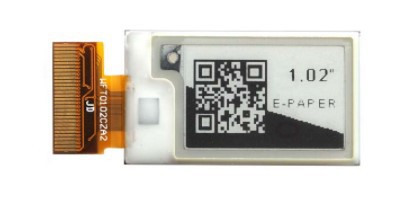
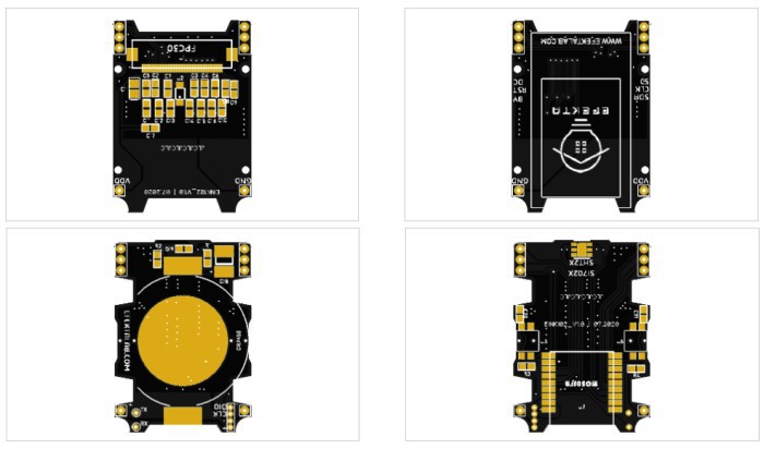
From the line of e-ink displays, the choice, of course, fell on a fairly new model with a screen size of 1.02 inches. The cost of one inch of e-ink was $ 7, which I found acceptable. A little difficulty in developing a board for this display was caused by a connector - a 30-pin FPC with a pitch of 0.5 mm. The width of the FPC connector is much larger than the width of the display itself, which caused inconvenience when designing pcb (datasheet GDEW0102T4).
From various digital temperature and humidity sensors, I decided to install a sht20 sensor. I had a lot of them, it's a fairly simple sensor, good price, convenient size. Also, one of the advantages is that instead of sht20, if desired, it is easy to install sht21, si7020, si7021, htu20d, htu21d.
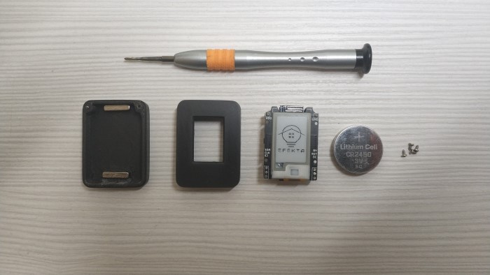
The device was designed on two pcb, one for the screen and its strapping, the other for the radio module, temperature and humidity sensor and battery. The key parameters for board size were screen and battery size. On the board with the screen there were holes for screws (1.4x3) for attaching the board to the case, on the second board there were cutouts for easy installation of the screws. Since this is a DIY device, I could afford to put in a tasty CR2450 battery. Well, if one day it seems to me that the device is fat, then I can always solder the holder for the CR2430 battery. As a result, we got two boards measuring 36mm by 26mm.
Then the case was designed, DXF board models were exported from DipTrace, which were converted into 3D models in the design program. The body consists of two parts and a button. The halves of the case are fastened together in the same way with screws (1.4 x 4) on one side and a protruding "hook" on the other. There are two openings for air circulation under the temperature and humidity sensor.
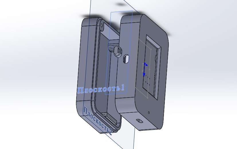
In this project, the body was printed on an FDM printer, the print quality is certainly lower than on an SLA printer, but in terms of strength, products made from liquid resins are much inferior to products made from threads. So, I was mentally prepared for the subsequent grinding and polishing. In principle, it turned out well.
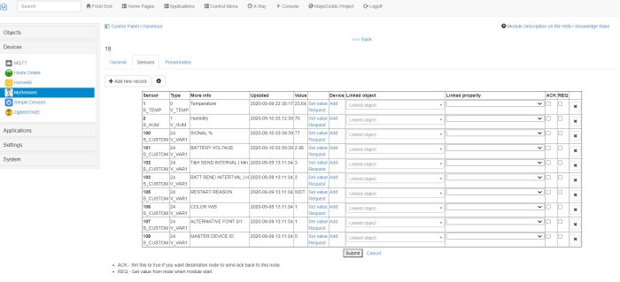
This is approximately how the development of hardware took place, I tried to describe all the stages and some of the nuances. If you thought it was time consuming, it is not. The software is what was really time consuming. As before, I make my projects under MySensors, although I admit that I am not as enthusiastic as I used to be.
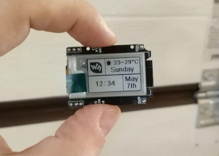
As a result, I was able to fulfill all my requirements for functionality. The device can work with the Smart Home controller. The sensor has support for several languages, color inversion by an external command in the device configuration mode, several font options, which can also be changed by an external command in the device configuration mode. The sensor displays temperature and humidity readings, battery level and signal strength on the screen. The interval for measuring temperature and humidity, the interval for measuring the battery charge level can also be set by an external command. For temperature and humidity in minutes, for battery level in hours. The sensor transmits the following data to the Smart Home system: temperature, humidity, charge level in%, voltage, signal level, reason for reboot.
You can see how it works in my small video:
Timestamps of interesting moments:
3.10 - Configuration (font change, color inversion)
5.10 - Metering consumption, WTD operation
If someone is interested in my developments, then after reading the article I recommend going to the channel and subscribing, where I publish information on new developments first of all.
In sleep mode, the sensor consumes 2μA, WTD reset every 5 seconds, consumption at the time of reset is 4-5μA. In the mode of operation with a screen and a temperature and humidity sensor of 2-3mA, in a transmission mode of 5-8mA, such a range of 3 mA is due to the fact that the sensor itself regulates the transmission power based on the signal level data.
Open Source Hardware | [OSHW] RU000002 | Certified Open Source Hardware