
I happened to need GΩ resistors for high-voltage stuff. And I like to measure things. I looked up how to measure GΩ resistors. Some people suggest applying a high voltage and measuring the current with the voltage function of a multimeter. I wanted to try if I could measure large resistances without using a high voltage or expensive instrument as an exercise.
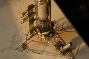
The device is mainly a triangle-wave oscillator like Figure 4.39 in The Art of Electronics (3rd edition). Its period is determined by the product of the integrating capacitance and the resistance to be measured. ±7.5V is applied across the resistor. The integrating capacitor is the capacitance of the coax that connects the opamp to the connector. Because I will want to shield that connection anyway. The cable is Belden 7806A RG-58/U foam polyethylene which is what I happened to have lying around. The times when the triangle wave crosses zero and reaches its peaks are recorded with an STM32F031C6T MCU. Resistance is derived from the time it takes the triangle wave to go from zero to the peaks. The time it goes from the peaks back to zero is not used, because the start of it will depend on the capacitance of the DUT. The opamp U1 needs to have low leakage current. I picked LMC662. As for the comparators U2 and U3, I didn't find any that offers rail-to-rail output and operates with a 15V supply. So I used LM393 with CD4069UB. The LM393 is under the banana plug socket in the photo.
The idea is to apply a low voltage across the large resistance and measure the small current. This current is even smaller than practical with a multimeter's voltage function. But it can still be measured by integrating it and measuring the speed of integration (What's All This Femtoampere Stuff, Anyhow?). What I didn't like about Bob Pease's setup was that the integrator had to be zeroed with a switch. I thought about removing a fixed amount of charge every time the integrator reaches a threshold like in a voltage-to-frequency converter. Then I realized I would have to prevent leakage the rest of the time. It's not a problem with higher currents. But here I would need tetraohms to petaohms of insulation if I don't want to degrade LMC662's low leakage current which potentially lets me measure above tetraohms with accuracy. That means a mechanical or electromechanical switch again. They are slower and have more jitter than FETs. So while they allow me to measure very high resistances, the lower end of what they allow me to measure is also higher than with FETs. And the jitter means I won't get the same precision by looking at the frequency alone, I would have to look at the integrator waveform. I thought for a while and realized I could switch the voltage input of the integrator.
To calibrate the device, I connected 10 10MΩ resistors in series. I measured them individually with a multimeter. Then I measured from one end of the chain to each node with the device. I also connected 80 10MΩ resistors in series and measured resistance in increments of 10 resistors. Noise plus integral nonlinearity is within 5% from 10MΩ to 800MΩ. As the chain of resistors grew longer it became harder to get a reading that doesn't depend on orientation and how close my hand was. And since I didn't intend to measure such long chains with the device, I didn't bother making a shield and stopped there.
Code and STM32Cube project files are provided.

 DeepSOIC
 mircemk
 John Duffy
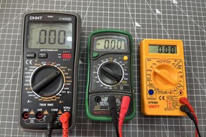
 Lithium ION
U2 and U3 is Mentioned Seperately.i tried to make it better here https://easyupload.io/qbejm0. Please Correct me if i am wrong.