This project was developed in partnership with Robô Lúdico Schooland JLCPCB Factory that offers 5 free PCBs of Arduino Compatible Board.
In commercial establishments, it is very common to use panels with LED arrays to display some information such as Product prices, welcome messages to customers, among other messages.
These matrices are very useful, as they are larger than LCD displays, Oled because they can be viewed from a distance.
So in this article, we will learn how to control this matrix through a mobile application that will be developed in MIT APP Inventor.
With this application, it will be possible to send personalized texts to be displayed in this matrix.
In this project, we will use 4 LED arrays connected in series to compose our panel.
You can use multiple arrays in this project. To do this, just make some changes to the code.
Therefore, through this article you will learn:
1 - Perform the assembly of the circuit on the protoboard;
2 - Communication of the Arduino with the Bluetooth module;
3 - Develop the mobile application using the APP Inventor;
4 - Understand the operation of the led matrix;
5 - Understand the functioning of the ci used to control this matrix.
Now, we will start the complete presentation of the project development Controlling a panel of led arrays through a mobile application.
DEVELOPING THE PROJECT CONTROLLING A LED MATRIX PANEL THROUGH A MOBILE APPLICATION
As previously mentioned, we developed firmware to control the LED arrays and write texts on them.
This text will be sent through an application installed on a cell phone and sent through the cell phone's Bluetooth communication with the Arduino Uno board.
You will receive this text and process it to be printed on the LED arrays.
Therefore, first, the firmware for the Arduino will be developed, and then the mobile application for the cell phone.
The project circuit with the LED matrix is shown in Figure 1.
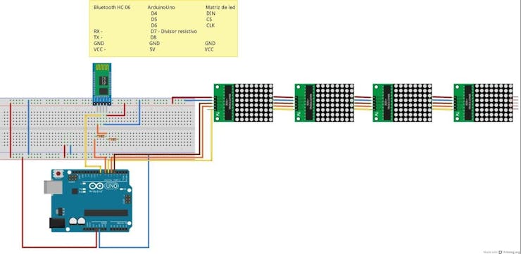
Figure 1 - Schematic circuit with the Bluetooth module connections and the LED arrays to the Arduino Uno.
In this circuit the Bluetooth module is powered with a voltage of 5 V at the VCC terminal, however, its logic level is 3.3 V.
For this reason, the RX terminal of the Bluetooth module requires a resistive divider to attenuate the 5V voltage, which comes from the Arduino Nano.
If you do not use the resistive divider, the module will burn over time.
To calculate the resistive divisor, equation 1 is used:
Vout = ( R2 / R1 + R2) x Vin
3.3 = (10.000 / R1 + 10000) x 5
3.3 R1 + 33000 = 50000
3.3 R1 = 50000 – 33000
3.3 R1 = 17.000
R1 = 17.000 / 3.3
R1 = 5 KΩ
Therefore, we will use a 5k resistor and a 10k resistor in our resistive divider with the assembled circuit.
Now, let's go to Arduino programming.
The Matrix Structure of 8x8 LEDs
The led matrix is a component that has 64 interconnected leds and distributed in 8 rows and 8 columns. The LED matrix is presented below.
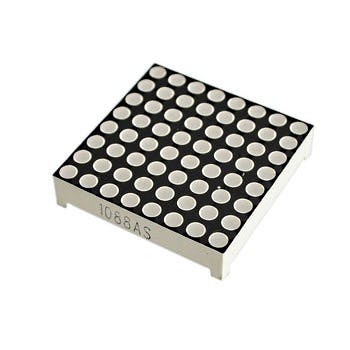
Figure 2 - The LED Matrix.
It is made in order to facilitate the individual activation of each led.
So instead of 65 pins, it has only 16 pins.
This solution is achieved by interconnecting the LEDs by rows and columns. The LEDs of each column have the anodes interconnected and the LEDs of each line have the cathodes interconnected. But this configuration can change depending on the type of matrix used.
Currently, there are two types of the matrix on the market: common anode and common cathode.
In figure 3 we have the scheme of the two possible connections in a led matrix.

Figure 3 - Possible connections in a led matrix.
The figure on the left is a common cathode matrix and the other is a common anode.
Performing the matrix drive in this way would use many uC pins, so it is not very feasible.
That way we will use a ready-made module that has a Ci Max 7219. It is dedicated to controlling this matrix using only 3 pins: Din, CS, CLK.
Using this ci we can control the 4 LED arrays using only 3 pins of the Arduino board. It, too, can be used to control 7-segment displays. For this, it receives and sends the received data serially to the led matrix or the 7-segment display.

In figure 5 we have the led matrix module with CI Max 7219.

Figure 5 - 8 x8 led matrix module with ci MAX 7219.
After understanding the operation of the LED matrix, we will program the Arduino to control the matrices.
Development of the project control logic
This project was developed with our Arduino-based board. You can download all the files and build your own Arduino-based board.
This project was developed with our Arduino-based board. You can download all the files and build your own Arduino-based board.
For this project, we'll use the JLCPCB Arduino Compatible printed circuit board presented below.

You can obtain the Arduino JLCPCB compatible PCB for your projects for $2 in your first order with the link: Earn my PCBs Arduino Compatible.
Use the JLC-RECE coupon,earn a $2 off discount, and earn 5 PCBs.
To develop this code it will be necessary to use two libraries:
The serial software, which emulates serial communication pins on the Arduino Uno board and the MD_MAX72xx, is the library that has the necessary functions to control the LED arrays.
The MD_MAX72xx library does not come, by default, in the Arduino IDE. For this reason, it is necessary to download and include it in the Arduino IDE.
After including both libraries, we will develop the code. The full code is presented below.
#include <MD_MAX72xx.h>#include <SoftwareSerial.h>SoftwareSerial HC06(8,7);#define MAX_DEVICES 4#define CLK_PIN 6 // or SCK#define DATA_PIN 4 // or MOSI#define CS_PIN 5 // or SS// SPI hardware interface//MD_MAX72XX mx = MD_MAX72XX(CS_PIN, MAX_DEVICES);// Arbitrary pinsMD_MAX72XX mx = MD_MAX72XX(DATA_PIN, CLK_PIN, CS_PIN, MAX_DEVICES);#define SCROLL_DELAY 50 // in milliseconds#define CHAR_SPACING 3 // Global message buffers shared by Serial and Scrolling functions#define BUF_SIZE 75char curMessage[BUF_SIZE];char newMessage[BUF_SIZE];bool newMessageAvailable = false;uint16_t scrollDelay; // in millisecondsvoid readSerial(void){ static uint8_t putIndex = 0; while (HC06.available()) { newMessage[putIndex] = (char)HC06.read(); if ((newMessage[putIndex] == '\n') || (putIndex >= BUF_SIZE-3)) { newMessage[putIndex++] = ' '; newMessage[putIndex] = '\0'; putIndex = 0; newMessageAvailable = true; } else // Just save the next char in next location newMessage[putIndex++]; }}void scrollDataSink(uint8_t dev, MD_MAX72XX::transformType_t t, uint8_t col)// Callback function for data that is being scrolled off the display{#if PRINT_CALLBACK Serial.print("\n cb "); Serial.print(dev); Serial.print(' '); Serial.print(t); Serial.print(' '); Serial.println(col);#endif}uint8_t scrollDataSource(uint8_t dev, MD_MAX72XX::transformType_t t){ static char *p = curMessage; static uint8_t state = 0; static uint8_t curLen, showLen; static uint8_t cBuf[8]; uint8_t colData; switch(state) { case 0: showLen = mx.getChar(*p++, sizeof(cBuf)/sizeof(cBuf[0]), cBuf); curLen = 0; state++; if (*p == '\0') { p = curMessage; if (newMessageAvailable) { strcpy(curMessage, newMessage); newMessageAvailable = false; } } case 1: // display the next part of the character colData = cBuf[curLen++]; if (curLen == showLen) { showLen = CHAR_SPACING; curLen = 0; state = 2; } break; case 2: // display intercharacter spacing (blank column) colData = 0; curLen++; if (curLen == showLen) state = 0; break; default: state = 0; } return(colData);} void scrollText(void){ static uint32_t prevTime = 0; // Is it time to scroll the text? if (millis()-prevTime >= scrollDelay) { mx.transform(MD_MAX72XX::TSR); prevTime = millis(); }}void setup(){ mx.begin(); mx.setShiftDataInCallback(scrollDataSource); mx.setShiftDataOutCallback(scrollDataSink); HC06.begin(9600); strcpy(curMessage, "ARDUINO "); newMessage[0] = '\0'; Serial.begin(9600); Serial.print("\n Texto matriz ");}void loop() { scrollDelay = 20; readSerial(); scrollText();}
First we include the MD_MAX72xx.h libraries and the Serial software.
#include <MD_MAX72xx.h>#include <SoftwareSerial.h>
Creates the serial communication pins, pin 8 is the RX pin, and pin 7 is the TX.
SoftwareSerial HC06(8,7);
Now the number of matrices that we will use in the project will be defined. We configured 4 matrices for this project.
#define MAX_DEVICES 4
Next, we map the pins connected to the LED matrix module.
#define CLK_PIN 6#define DATA_PIN 4#define CS_PIN 5
In this line, we configure the pins used to communicate the arrays with the Arduino.
MD_MAX72XX mx = MD_MAX72XX(DATA_PIN, CLK_PIN, CS_PIN, MAX_DEVICES);
In this line, we define the scrolling time of the text in the matrix.
#define SCROLL_DELAY 50
Next, we define the number of pixels of space between one text and another in the matrix.
#define CHAR_SPACING 3
In the next lines, we define the size of the buffer to store the text received through serial communication.
#define BUF_SIZE 75
In this line, we declare variables of type char to store the text received through serial communication.
char curMessage[BUF_SIZE];char newMessage[BUF_SIZE];bool newMessageAvailable = false;uint16_t scrollDelay; // in milliseconds
Next, we have the function that will perform the reading of the serial port to receive the text sent.
void readSerial (void){ //Static variable of unsigned integer type, this variable will store the message index. static uint8_t putIndex = 0; //While the HC06 serial is available, the newMessage variable will store the text received by the serial. while (HC06.available ()) { //Reads the serial port. newMessage [putIndex] = (char) HC06.read (); //If newMessage is equal to \ n it means that the text has been sent completely and at the end came the line break \ n or if the putIndex is equal to 72. if ((newMessage [putIndex] == '\ n') || (putIndex> = BUF_SIZE-3)) // end of message character or full buffer { //put in a message separator and end the string newMessage [putIndex ++] = ''; newMessage [putIndex] = '\ 0';Reset the index waiting for the next message received. putIndex = 0; newMessageAvailable = true; } //If it does not increase the message index. else // Just save the next char in next location newMessage [putIndex ++]; }}
After that, we have the function that performs the scrolling of the text in the matrix.
void scrollText (void){ static uint 32 prevTime = 0 //This variable will store the time in millis to perform the matrix roll. static uint32_t prevTime = 0; //If millis - prevTime is greater than the scrollDelay constant, the text scrolls to the right in the matrix. if (millis () - prevTime> = scrollDelay) { mx.transform (MD_MAX72XX :: TSR); prevTime = millis (); // starting point for next time }}
To perform the displacement we have two parameters: TSR and TSL. With TSR we move the text to the right, with TSL we move the text to the left.
mx.transform(MD_MAX72XX::TSR);
In the void setup function, serial communication speed, communication with the LED matrix is configured.
Write the text that will be written in the matrix if you don't send anything through the application.
void setup(){mx.begin(); // Inicia comunicação com a matrizmx.setShiftDataInCallback(scrollDataSource); //Function that will receive the text to be written in the matrixmx.setShiftDataOutCallback(scrollDataSink); //Function that will write the text in the matrixHC06.begin(9600); //Sets the serial communication speed with the bluetooth modulestrcpy(curMessage, "ARDUINO "); //Message that will be written in the matrixnewMessage[0] = '\0'; //Indicates that the message has reached the endSerial.begin(9600); //Sets the serial communication speed with the serial monitor.Serial.print("\n Matrix Text ");}
In the void loop function, the Bluetooth serial port is read, writes to the matrix, and scrolls the text in the matrix.
void loop(){ scrollDelay = 20; readSerial(); scrollText();}
After developing the firmware for the Arduino, we will develop the application for the cell phone to be able to send texts to the matrix.
Developing the app on AppInventor
The MIT app inventor is a block programming platform for developing mobile applications and it can be accessed through the website https://appinventor.mit.edu/.

Figure 6 - AppInventor Website.
Create a google account, access the platform, and click on Create apps.
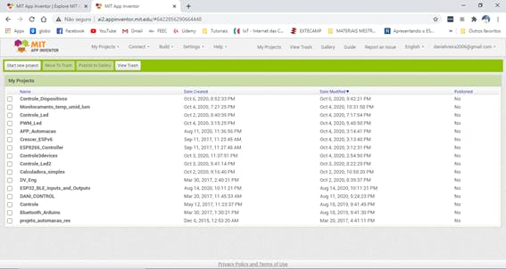
Figure 7 - App Inventor home screen.
Click Start new projects to start creating a new project.
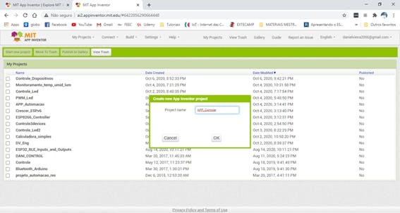
Figura 8 – Criando um novo projeto no App Inventor
The App Inventor is divided into two parts: graphics and blocks. The graphic part, as shown in figure 9, creates screens with buttons, different colors, communication modes, and other features. This is seen in figure 9.

Figure 9 - Graphic part of APP Inventor.
The block part is where we carry out the programming of our application.
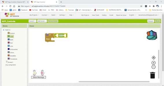
Figure 9 - App Inventor block programming part.
After starting a new project, we will use the component in a horizontal organization layout.
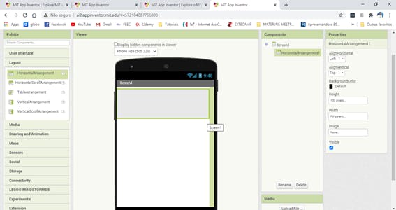
Figure 10 - Creating a new app.
It is possible to change the size of the horizontal organization, color, position. In the user interface, we will choose a button.
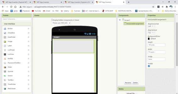
Figure 11 - Choosing a button in APP Inventor
You can choose the properties of the size button, add an image, and enlarge the font.
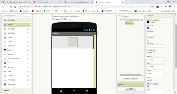
Figure 12 - Button in APP Inventor.
In connectivity, we will choose Bluetooth client.
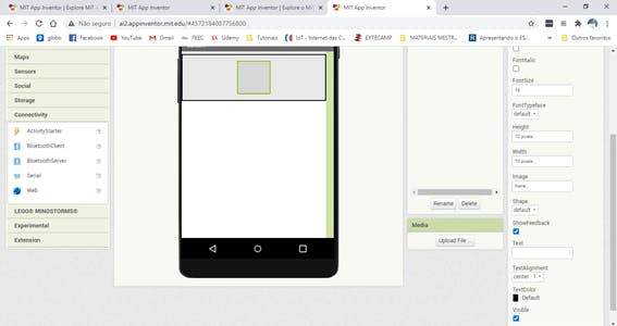
Figure 13 - Bluetooth client.
Clicking on Active Starter in action put the instruction presented below.
android.bluetooth.adapter.action.REQUEST_ENABLE
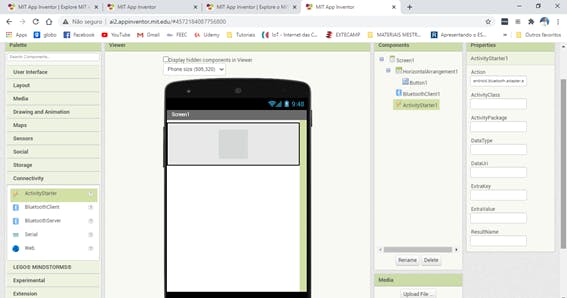
Figurae 14 – Active Starter.
We will use the textbox component to write a text that will be sent to the LED matrix. The application screen layout will be as shown in figure 15.

Figure 15 - Screen App.
After finishing the aesthetic part of the application, we go to the application programming using the APP Inventor block language.
When the application is opened, the application checks whether Bluetooth is enabled, if not, it asks to enable as shown in figure 16.
When the connect button is pressed it performs a series of checks, opens a list of paired devices, and allows the user to choose which device to connect to and connects to Bluetooth.
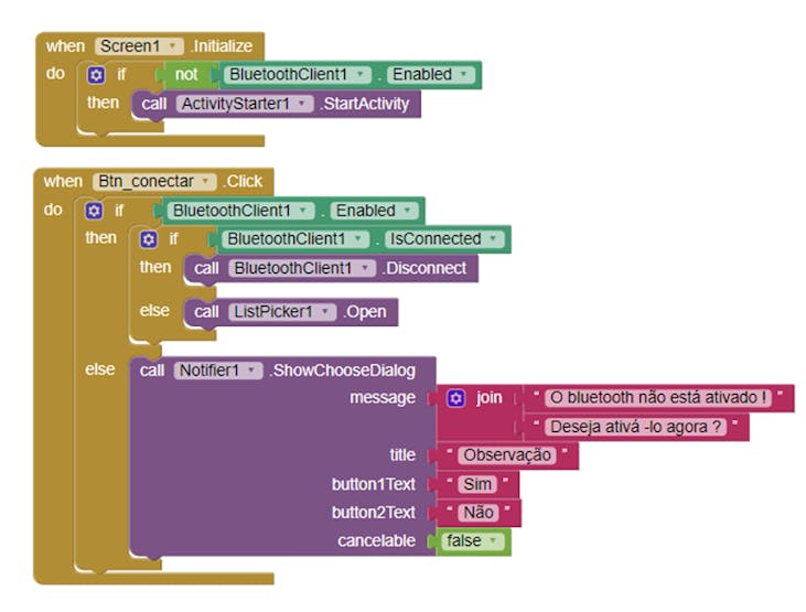
Figure 16 - Logic programming.
Before connecting, set up to display the paired devices. The logic is shown in figure 17.
Then the notification appears after connecting to the device.

Figure 17 - Code of the list of paired devices
Notification that enables Bluetooth if it is disabled when the application is opened.
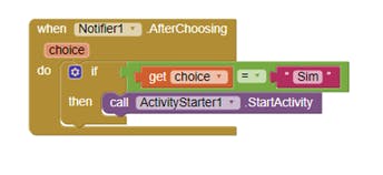
Figure 18 - Code to enable bluetooth if it is disabled.
When the button sends text is pressed, the APP checks if the Bluetooth is connected if there is no notification asking you to connect to Bluetooth.
If connected, Bluetooth sends the text in the text box and then sends the character \ n that indicates the end of the message as explained in the Arduino code.
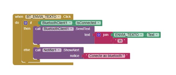
Figure 19 - Code for when the button sends text is pressed
To use this application on your phone, you need to install the MIT AI2 Companion application available on the Playstore on your phone.
With this app, we will scan the QR code generated by our app and install our app developed on the phone.

Figure 20 - Mit AI2 Companion application.
With this application, we will scan the QR code of our application generated by the platform.
On the website click on build and QR Code.

Figure 21 - Generating QR code of the developed application.

Figure 22 - QR code of the developed application
To install the application on your phone, you must release the option to install applications from unknown sources.
With the application installed on the phone and the Arduino programmed we will test the project.
Now, let's look at the outcome of the project.
Project results
When opening the application it connects to the Bluetooth connection to the Arduino.
With the Bluetooth connection, we will type the text in the field and click on the arrow to send the text to the Arduino write on the led matrix.
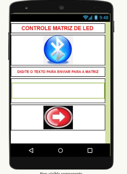
Figure 23 - Application developed.
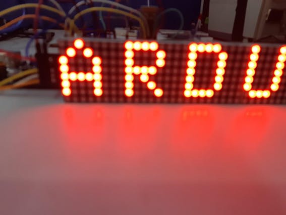
Figure 24 - Text being displayed in the matrix.
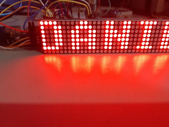
Figure 25 - Text being displayed in the matrix.
Acknowledgments
We thank the company JLCPCB - Printed Circuit Board Factory and Robô Lúdico School for the support and partnership in the development of this project.
We thank the Robô Lúdico School In Brazil to create several projects and courses about robotics and Arduino.
We leave a link for you to purchase your printed circuit boards for a value of $ 2 through that link. Use the JLC-RECE coupon, earn a $2 off discount, and earn 5 PCBs.