This project was developed in partnership with Robô Lúdico School and JLCPCB Factory that offers 5 free PCBs of Arduino Compatible Board.
I want to teach you how to communicate with 3 Arduino boards or up to 32 on a communication network. This process is possible thanks to the use of the RS-485 physical layer.
This physical medium is built through the MAX485 integrated circuit, which is responsible for converting the Arduino TTL serial signal to the RS-485 physical medium signal.
What project will you develop?
The project consists of 3 Arduino's. We have an Arduino UNO, a Nano, and a MEGA. The Arduino UNO will control the other 2 and send commands to receive the reading of the analog signal from the potentiometer connected to each Arduino.
He will receive the signal and present it on the LCD screen.
This communication will be developed through the use of RS-485 modules. See the circuit below.

The MAX485 can transmit this data over a distance of 1200 m, in addition, it has high immunity to electromagnetic interference. This is one of the reasons why it is widely used by industrial devices, such as programmable logic controllers.
To make this communication we use the Arduino MAX485 module. This module will allow us to interconnect the devices and carry out our communication. See the photo of the module.
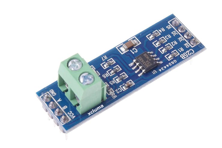
The board presents the complete circuit for you to transfer and receive data between the boards. The connecting pins are quite easy for you to learn.
Observe the figure and see that it is formed by 8 pins: DI, DE, RE,R0,VCC, A, B, and GND.
Shall we understand the function of each of them?
Pins DI and R0 are used to transmit data (DI - Data Input) and receive data (RO - Received Output). Connect the TX pin to the DI and the RX to the RO.
The configuration of the data transfer or reception mode is done through the DE and RE pins. The first thing you must do is connect the pins with a jumper.
Then, you must apply 5V to put the circuit in transfer mode and 0V to receive data. See the circuit in the figure and analyze the connection on the DE and RE pins.
In addition to these pins, we have VCC, A, B, and GND. The VCC and GND are used to supply the module circuit, while A and B will be responsible for transmitting information from one module to another with RS-485 voltage levels.
All pins of Letter A must connect to each other. This rule also applies to B.
Now you will learn the programming logic and the complete circuit for this project.
For this project, we'll use the JLCPCB Arduino Compatible printed circuit board presented below.
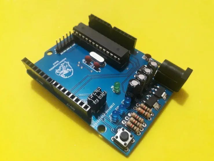
You can obtain the Arduino JLCPCB compatible PCB for your projects for $2 in your first order with the link: Earn my PCBs Arduino Compatible.
Use the JLC-RECE coupon,earn a $2 off discount, and earn FREE5 PCBs.
The project control logic
The logic is divided into two parts. We have the control logic of the Arduino Master and that of the slave Arduino's.
What is a master and slaves?
The master Arduino is responsible for the communication control, that is, only he can initiate communication with the slaves. In our project, Arduino UNO is the master of this communication.
Slave Arduino's only obey commands sent by the master. Arduino NANO and MEGA are Arduino's slaves.
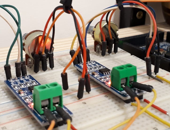
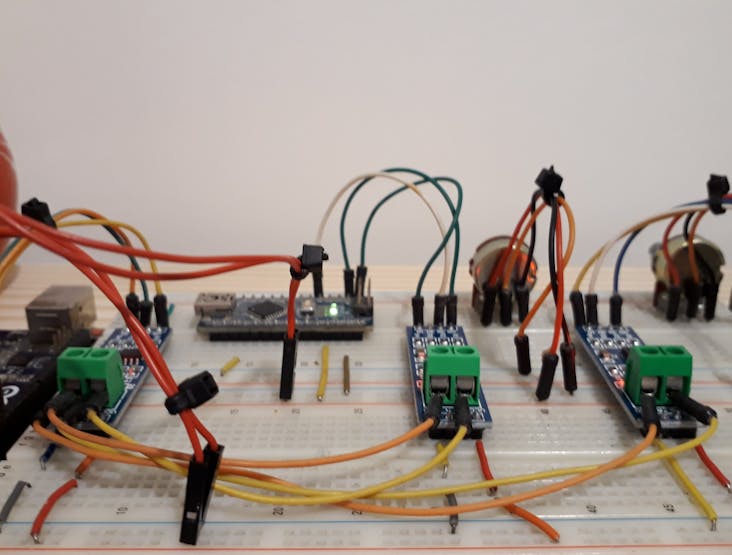
See the figure below. We present 2 potentiometers. Each one is connected to each slave.
Now, see the code of the master Arduino.
#include <LiquidCrystal_I2C.h> //Biblioteca I2C do LCD 16x2LiquidCrystal_I2C lcd(0x27,16,2); // Configurando o endereco do LCD 16x2 para 0x27int value1 = 0, value2 = 0;const int LED = 13; const int Enable = 2;void setup() { Serial.begin(9600); Serial.setTimeout(250); pinMode(LED, OUTPUT); pinMode(Enable, OUTPUT); digitalWrite(LED, LOW); digitalWrite(Enable, HIGH); lcd.init(); lcd.backlight();} void loop() { Serial.print("I"); Serial.print("1"); Serial.print("L"); Serial.print("F"); Serial.flush(); digitalWrite(Enable, LOW); if(Serial.find("i")) { int slave1 = Serial.parseInt(); value1 = Serial.parseInt(); if(Serial.read() == 'f' && slave1 == 1) { lcd.setCursor(0,0); lcd.print("Escravo 1: "); lcd.setCursor(11,0); lcd.print(value1); } } digitalWrite(Enable, HIGH); Serial.print("I"); Serial.print("2"); Serial.print("L"); Serial.print("F"); Serial.flush(); digitalWrite(Enable, LOW); if(Serial.find("i")) { int slave2 = Serial.parseInt(); value2 = Serial.parseInt(); if(Serial.read() == 'f' && slave2 == 2) { lcd.setCursor(0,1); lcd.print("Escravo 2: "); lcd.setCursor(11,1); lcd.print(value2); } } digitalWrite(Enable, HIGH);}
Initially we included libraries and declared all the variables of the project. See the code portion below.
#include <LiquidCrystal_I2C.h> //Biblioteca I2C do LCD 16x2LiquidCrystal_I2C lcd(0x27,16,2); // Configurando o endereco do LCD 16x2 para 0x27int value1 = 0, value2 = 0;const int LED = 13; const int Enable = 2;
In the setup function, we perform the configuration of the digital pins and set the enable pin to high logic level, to put the module in data transmission mode. See the code portion below.
void setup() { Serial.begin(9600); Serial.setTimeout(250); pinMode(LED, OUTPUT); pinMode(Enable, OUTPUT); digitalWrite(LED, LOW); digitalWrite(Enable, HIGH); lcd.init(); lcd.backlight();}
After that, we have the main logic of the project.
void loop() { Serial.print("I"); Serial.print("1"); Serial.print("L"); Serial.print("F"); Serial.flush(); digitalWrite(Enable, LOW); if(Serial.find("i")) { int slave1 = Serial.parseInt(); value1 = Serial.parseInt(); if(Serial.read() == 'f' && slave1 == 1) { lcd.setCursor(0,0); lcd.print("Escravo 1: "); lcd.setCursor(11,0); lcd.print(value1); } } digitalWrite(Enable, HIGH); Serial.print("I"); Serial.print("2"); Serial.print("L"); Serial.print("F"); Serial.flush(); digitalWrite(Enable, LOW); if(Serial.find("i")) { int slave2 = Serial.parseInt(); value2 = Serial.parseInt(); if(Serial.read() == 'f' && slave2 == 2) { lcd.setCursor(0,1); lcd.print("Escravo 2: "); lcd.setCursor(11,1); lcd.print(value2); } } digitalWrite(Enable, HIGH);}
In the first lines of code, the Arduino master send a message to read the slave sensor 1.
See the code block below.
Serial.print("I"); Serial.print("1"); Serial.print("L"); Serial.print("F"); Serial.flush();
Each character represents a different thing, see.
- I represent the beginning of the communication;
- 1 represents the slave number;
- L determines the sensor reading;
- F represents the end of the message transmission.
After transmission, the communication mode pin is set to a low logic level. This serves to prepare the master to receive the information that will be sent by Arduino Slave 1.
digitalWrite(Enable, LOW);
Then the Arduino master waits to receive the character "i". This character signals the start of the response sent by slave 1.

Figure 1 - Slave 1 sending the analog value for master.
After that, it will receive slave number 1, the value of the analog signal, and the letter f, which signals the end of data transmission from slave 1. See the code below.
if(Serial.find("i")) { int slave1 = Serial.parseInt(); value1 = Serial.parseInt(); if(Serial.read() == 'f' && slave1 == 1) { lcd.setCursor(0,0); lcd.print("Escravo 1: "); lcd.setCursor(11,0); lcd.print(value1); } }
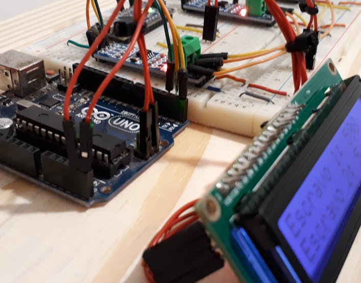
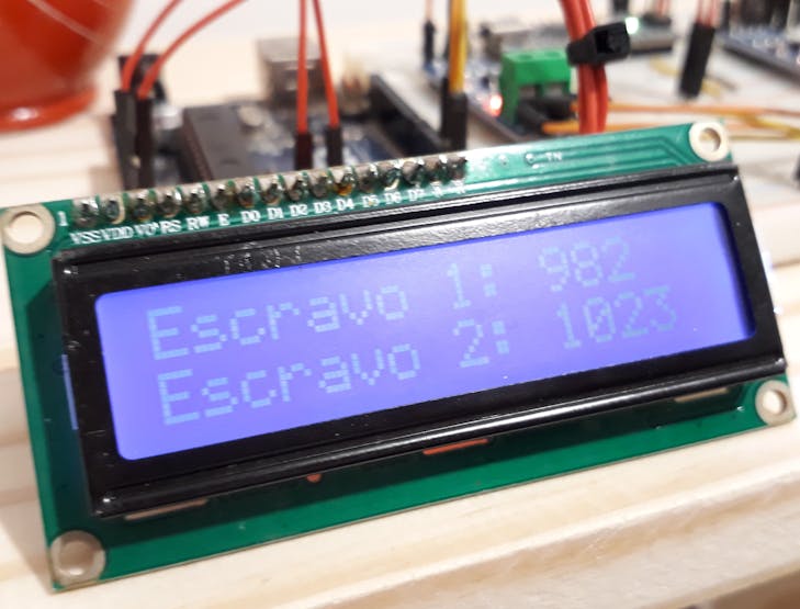
If the information received is from slave 1, the condition will be true and the Arduino will present the information received on line 1 of the LCD. See the image below.
The image below shows the result of the reading of slave 1 and slave 2 presented by the master.
After presenting the reading of slave 1, the code is repeated to read the analog signal on slave 2. See slave 2 below.

The code for reading the signal from slave 2 is the same as the code portion shown previously. See the code block below.
digitalWrite(Enable, HIGH); Serial.print("I"); Serial.print("2"); Serial.print("L"); Serial.print("F"); Serial.flush(); digitalWrite(Enable, LOW); if(Serial.find("i")) { int slave2 = Serial.parseInt(); value2 = Serial.parseInt(); if(Serial.read() == 'f' && slave2 == 2) { lcd.setCursor(0,1); lcd.print("Escravo 2: "); lcd.setCursor(11,1); lcd.print(value2); } } digitalWrite(Enable, HIGH);
The format of the message sent is the same. The only difference is the slave code. In this case, we use the value 2, because we want to receive the reading from slave 2. See the message.
Serial.print("I"); Serial.print("2"); Serial.print("L"); Serial.print("F"); Serial.flush();
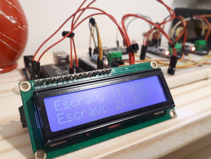
After sending this message, the Arduino master waits for the response from slave 2 and shows the value on the LCD screen. The result can be seen in the figure below.
Did you understand how the master's data transmission and reception process works? Now I am going to teach you how the slave reception code works.
Control code of the Arduino slaves
The slave Arduino code was built to receive and recognize the command sent by the master Arduino. The slave code is simple and is used for slave 1 and 2. See below.
const int Enable = 2; const int SlaveNumber = 1;void setup() { Serial.begin(9600); Serial.setTimeout(250); pinMode(Enable, OUTPUT); digitalWrite(Enable, LOW); pinMode(13, OUTPUT); pinMode(A0, INPUT);} void loop() { if(Serial.available()) { if(Serial.read()=='I') { int Slave = Serial.parseInt(); if(Slave == SlaveNumber) { char command = Serial.read(); if(command == 'L') { if(Serial.read()=='F') { int AnalogValue = analogRead(0); digitalWrite(Enable, HIGH); Serial.print("i"); Serial.print(SlaveNumber); Serial.print(AnalogValue); Serial.print("f"); Serial.flush(); digitalWrite(Enable, LOW); } } } } } delay(10);}
The first thing you define is a constant for the communication configuration pin for the RS-485 Module. After that, we inform the number of our slave. The code was used for slave 1. See the code below.
const int Enable = 2; const int SlaveNumber = 1;
The setup function is used to make the Arduino communication and digital pin configurations. In addition, you must put the MAX485 module in data reception mode, so that it starts ready to receive messages from the master.
digitalWrite(Enable, LOW);
In the main logic, the Arduino checks if any information has arrived in the serial.
if(Serial.available())
If the condition is true, it checks whether the character received is I.
if(Serial.read()=='I')
It understands that the master wants to start a communication. Then, it reads the number of the slave. This step is important, because it is through this number that he knows if the command is for him or for the other slave in the network.
int Slave = Serial.parseInt();if(Slave == SlaveNumber)
It compares the number received with your number and if it is true it enters the condition.
char command = Serial.read(); if(command == 'L') { if(Serial.read()=='F') {
Within the function it reads the command sent by the master and checks if its value is equal to L. If it is true, it understands that the master needs to read the analog signal. Finally, it reads the last character and checks if it is equal to F.
The letter F means that the message has ended. When the letter F is found it executes all the commands below and finally responds to the master.
int AnalogValue = analogRead(0); digitalWrite(Enable, HIGH); Serial.print("i");Serial.print(SlaveNumber); Serial.print(AnalogValue);Serial.print("f");Serial.flush(); digitalWrite(Enable, LOW);
The slave reads the analog signal from the potentiometer and stores it in the AnalogValue variable. Then, it puts the module to work in data transmission mode, to start transmitting the message to the master.
int AnalogValue = analogRead(0); digitalWrite(Enable, HIGH);
Finally, the message with the value read is sent to the master.
Serial.print("i");Serial.print(SlaveNumber); Serial.print(AnalogValue);Serial.print("f");Serial.flush();
O escravo envia a seguinte mensagem:
- I represents the beginning of the message
- SlaveNumber is the number of the slave that is responding
- AnalogValue is the signal value sent by the slave
- f represents the end of the message
After the end of the transmission, the slave configures the module to receive data mode and waits for new commands from the master.
Serial.flush(); digitalWrite(Enable, LOW);
This is how the communication and message exchange process between the master and the network of slaves works. See the connection circuit below.
This code is the same for any other slave. Change the number to add new slaves to your network.
const int SlaveNumber = 2;
We can put a limit of 31 slaves in this project.
Now it's time for you to put this project into practice and develop new ideas with this project. Did you like it? Have any questions? Leave your comment and like this project.
This helps me to know that you liked it and I will continue to post other projects for you.
Acknowledgment
I would like to thank Robô Lúdico School and the printed circuit board manufacturer JLCPCB for the support and support to develop this project.
Download your JLCPCB Arduino Compatible printed circuit board presented below.
You can obtain the Arduino JLCPCB compatible PCB for your projects for $2 in your first order with the link: Earn my PCBs Arduino Compatible.
Use the JLC-RECE coupon,earn a $2 off discount, and earn FREE5 PCBs.