0%
0%
DJI FPV Investigations
Things I've learned about the DJI FPV quadcopter.
 Duane Degn
Become a Hackaday.io member
Already have an account? Log in.
Just one more thing
To make the experience fit your profile, pick a username and tell us what interests you.
Pick an awesome username
hackaday.io/
Your profile's URL: hackaday.io/username. Max 25 alphanumeric characters.
Pick a few interests
Projects that share your interests
People that share your interests

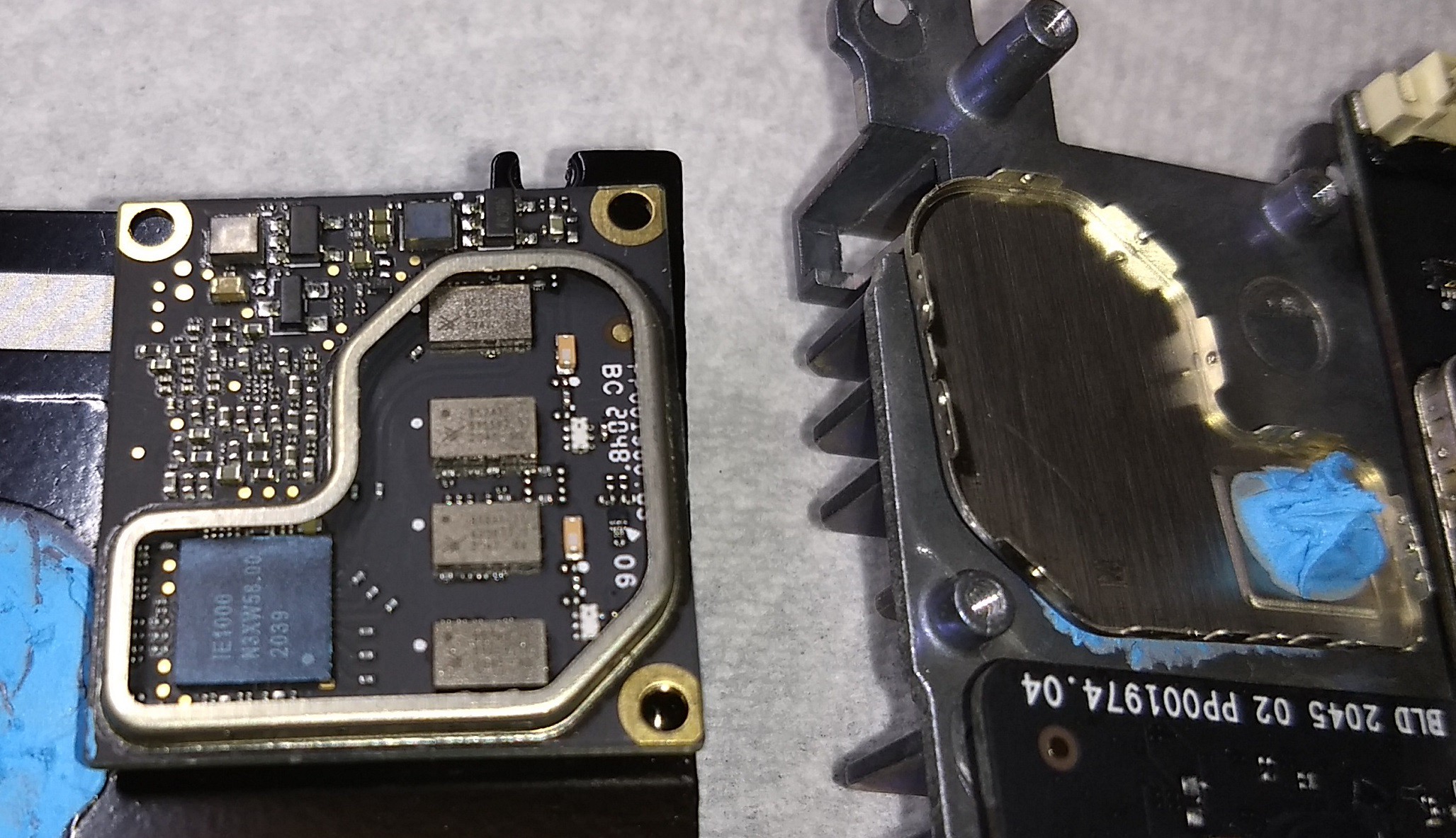

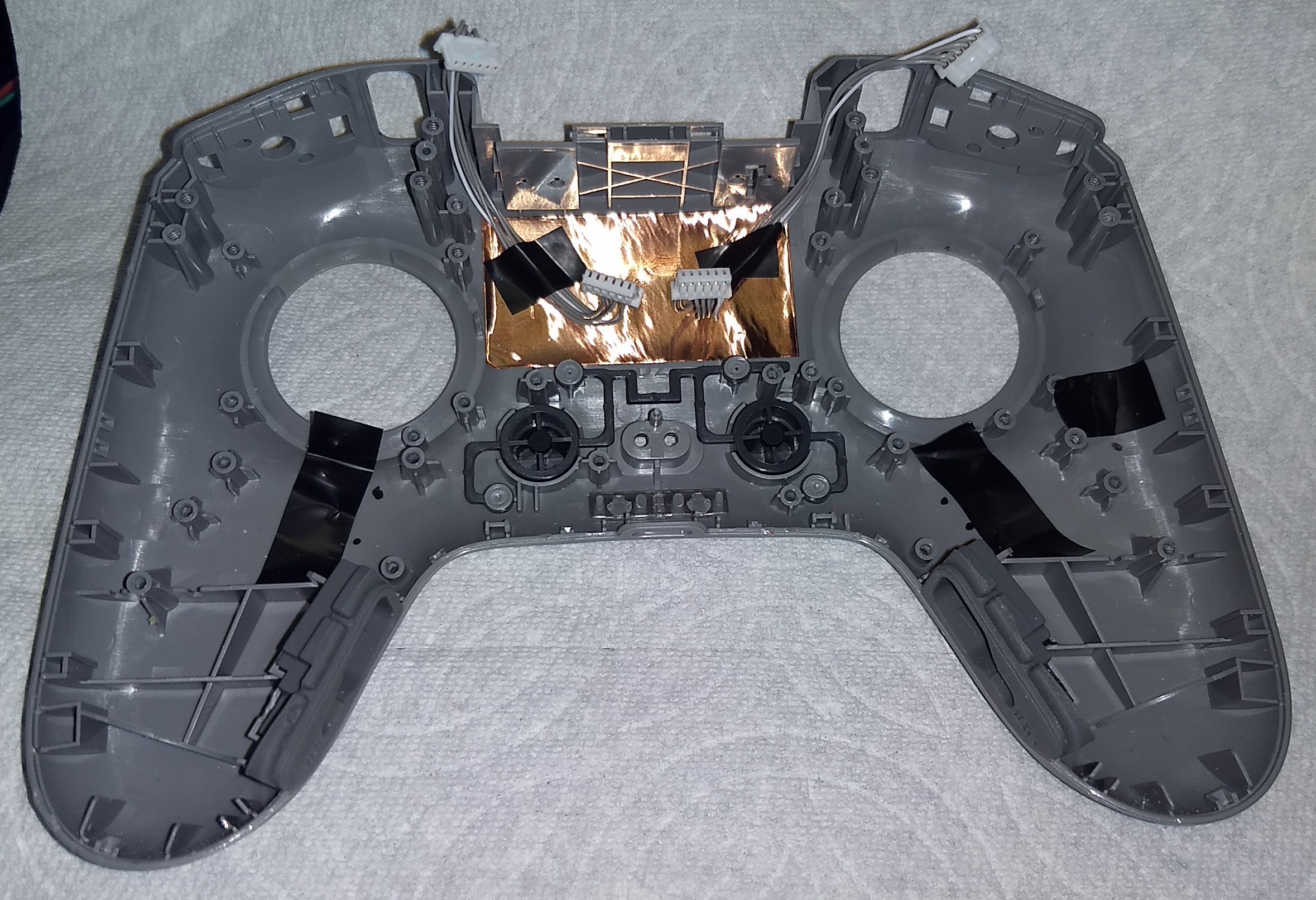
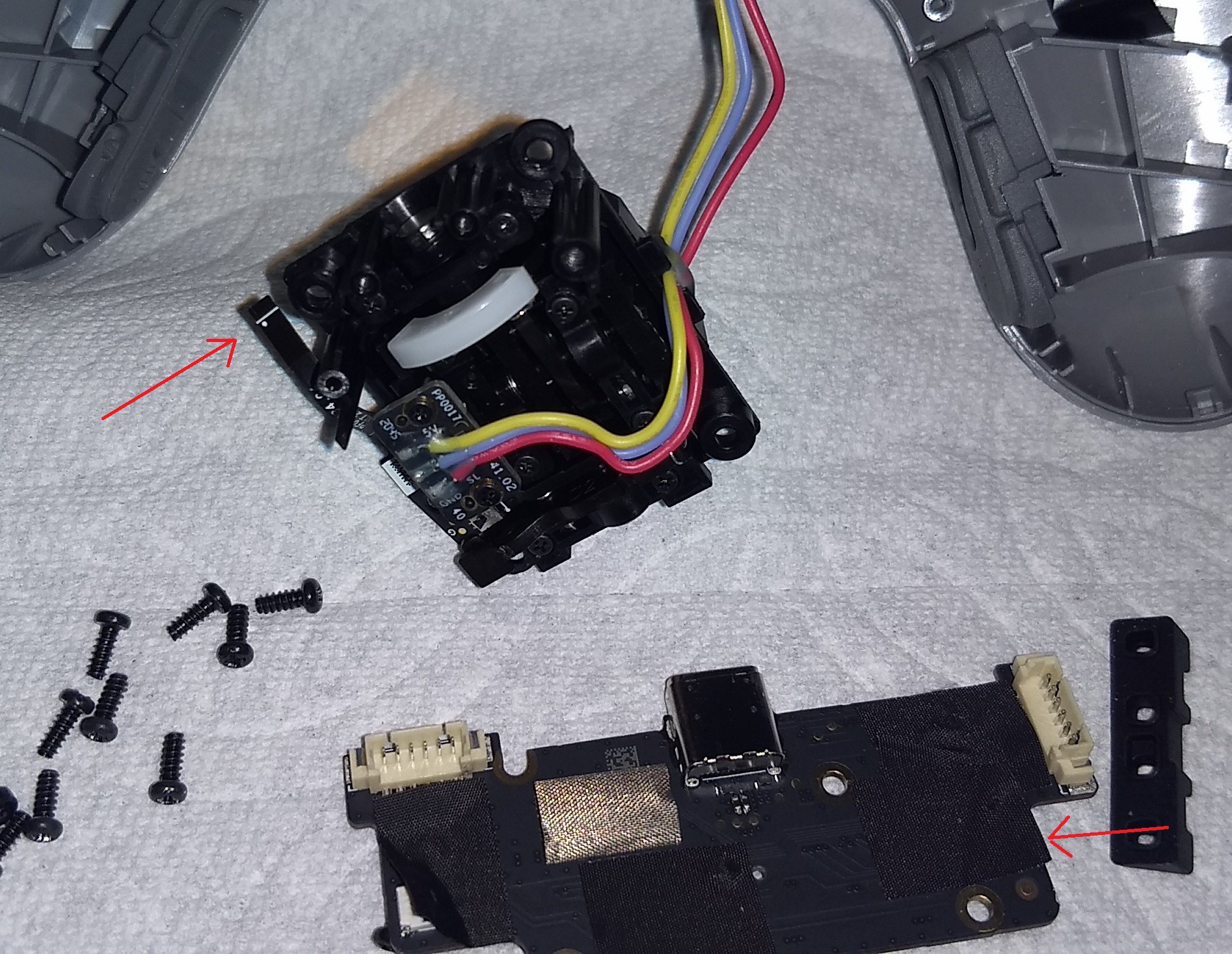
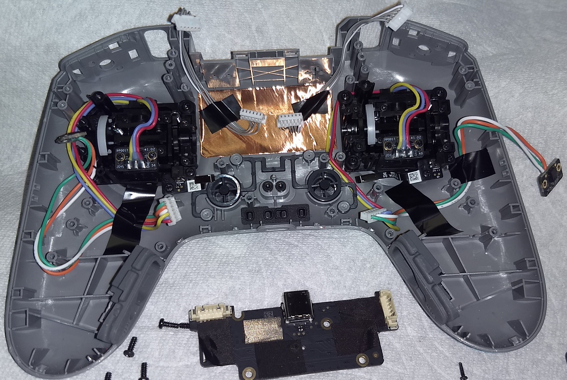
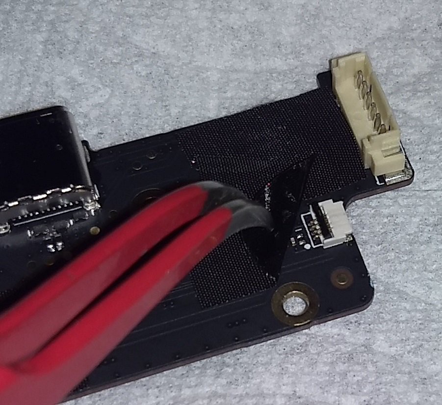
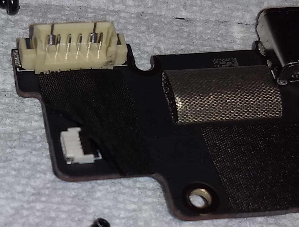
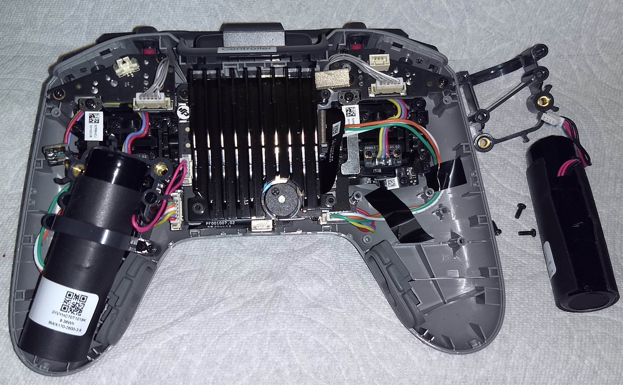
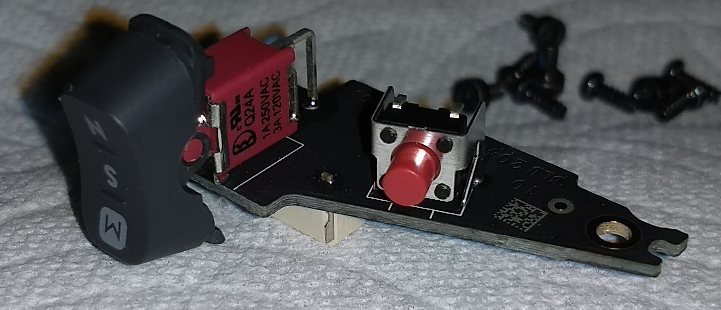
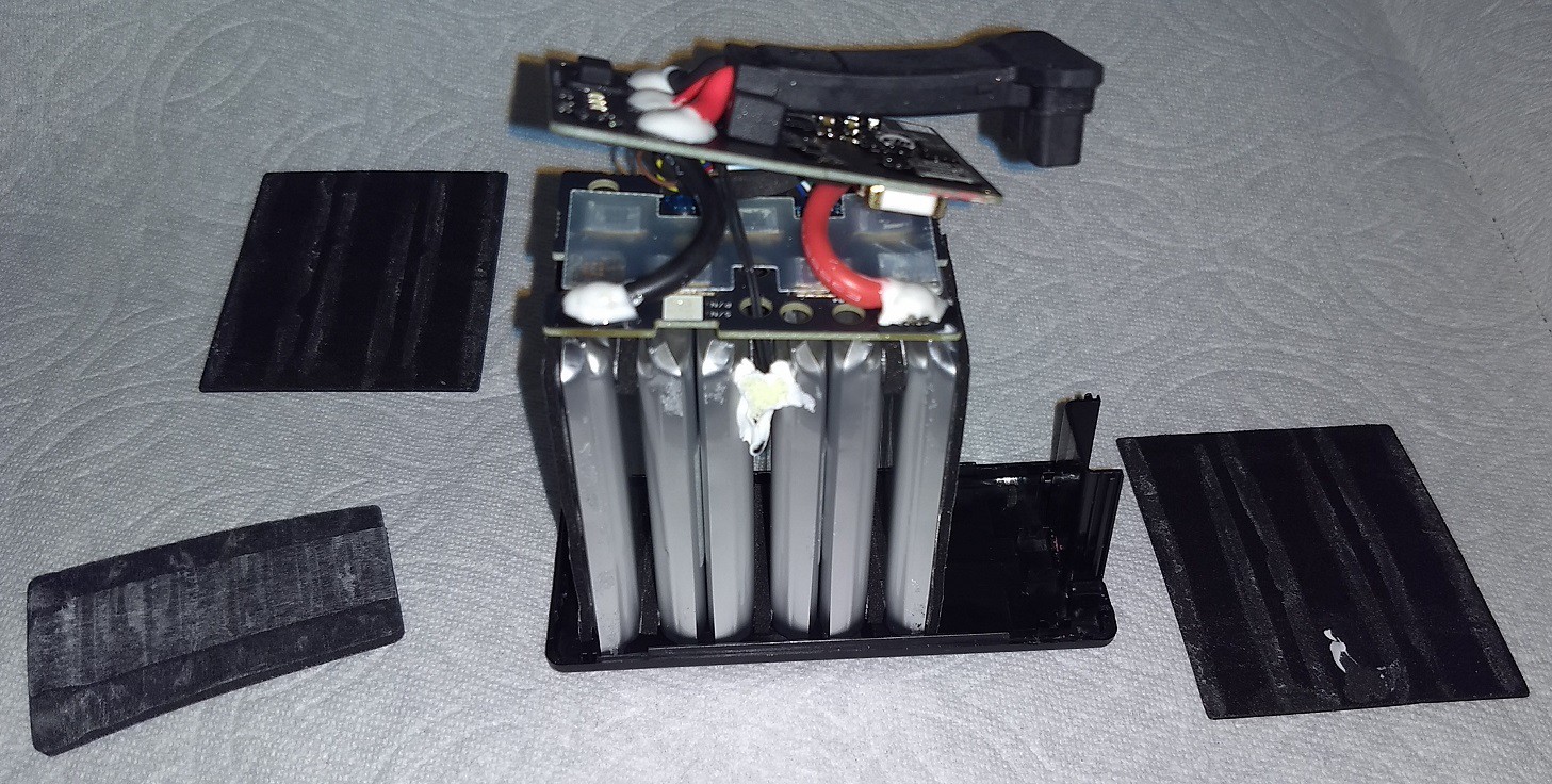
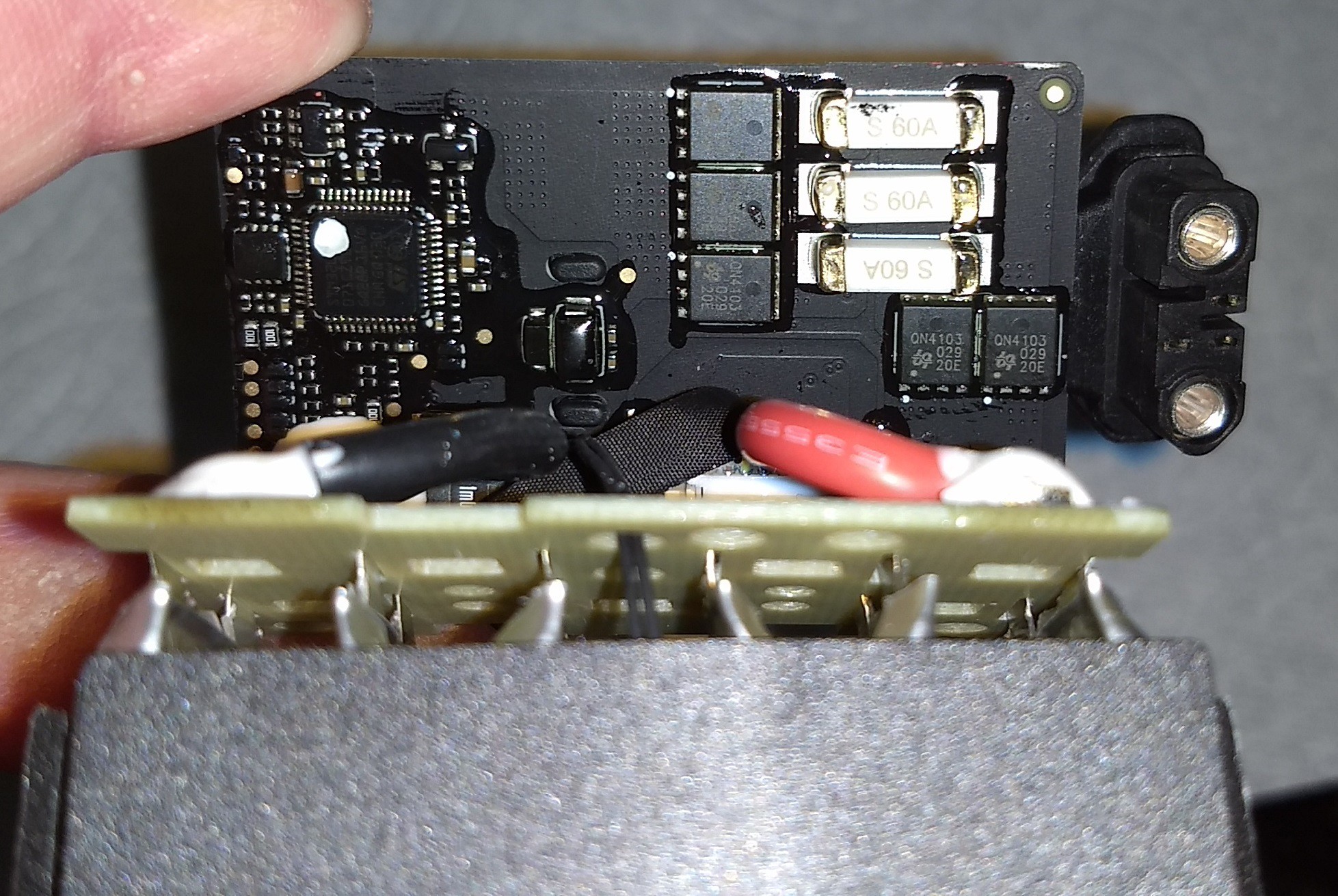
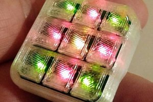
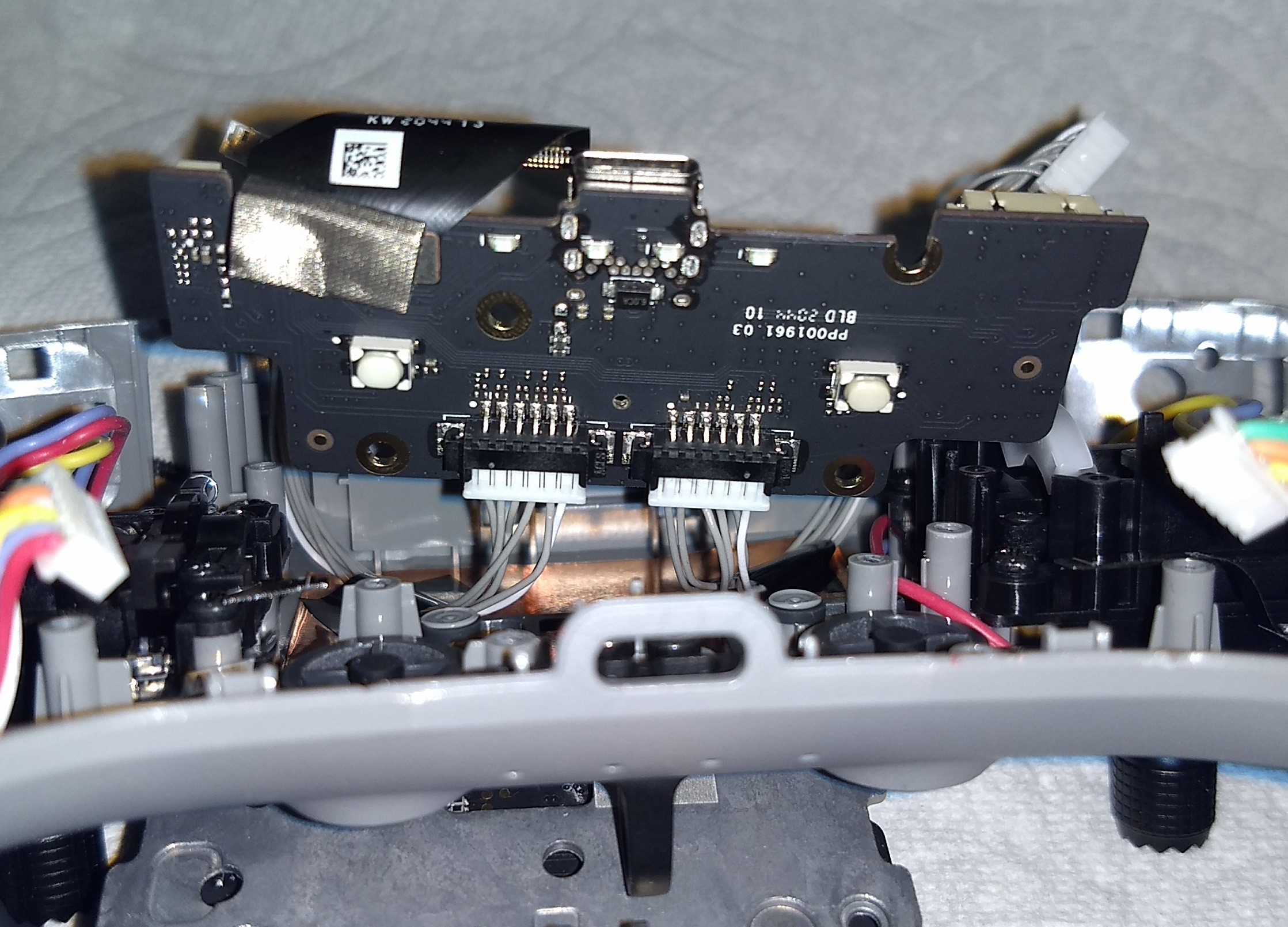 Above is the PBC which has the USB connection, two buttons, and the power LEDs.
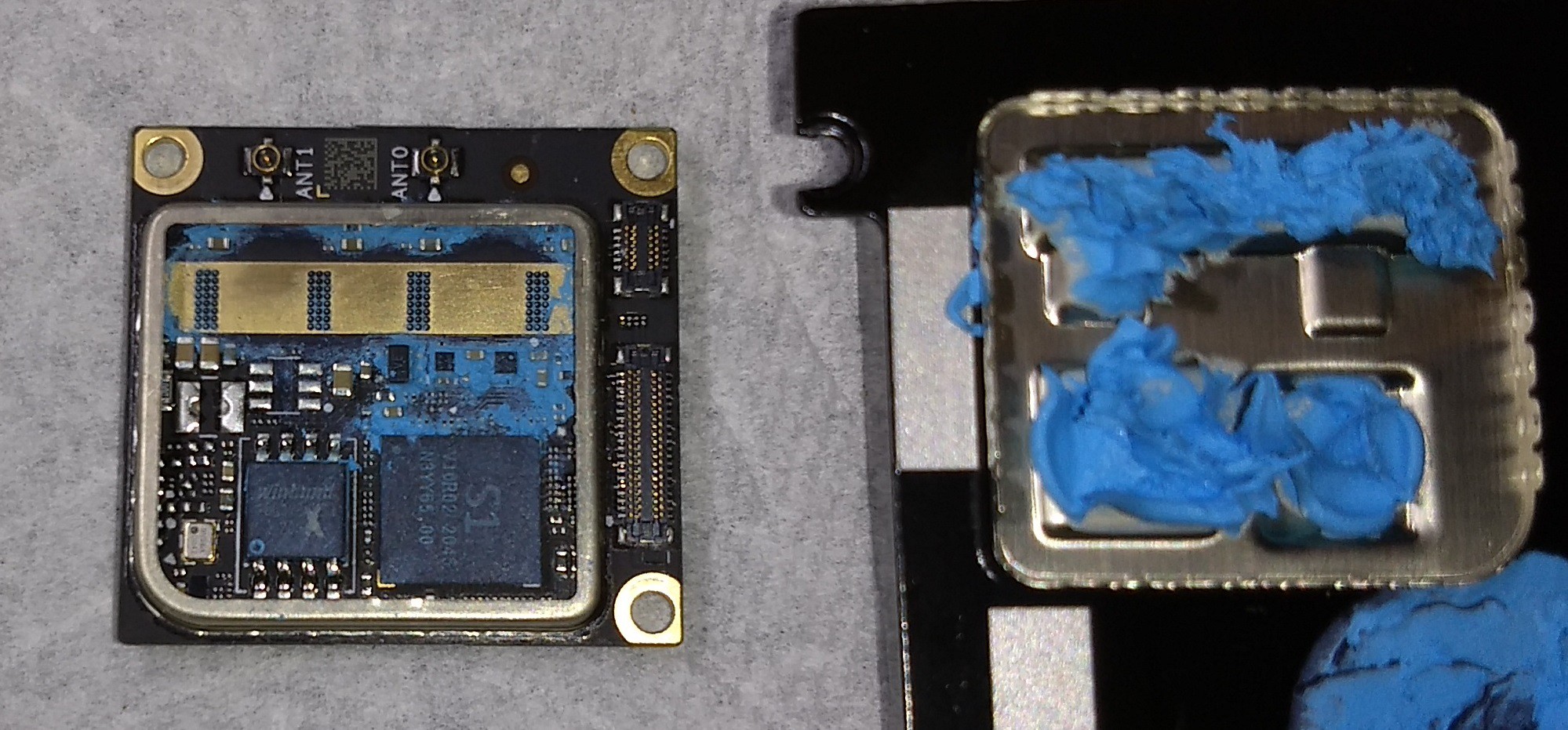
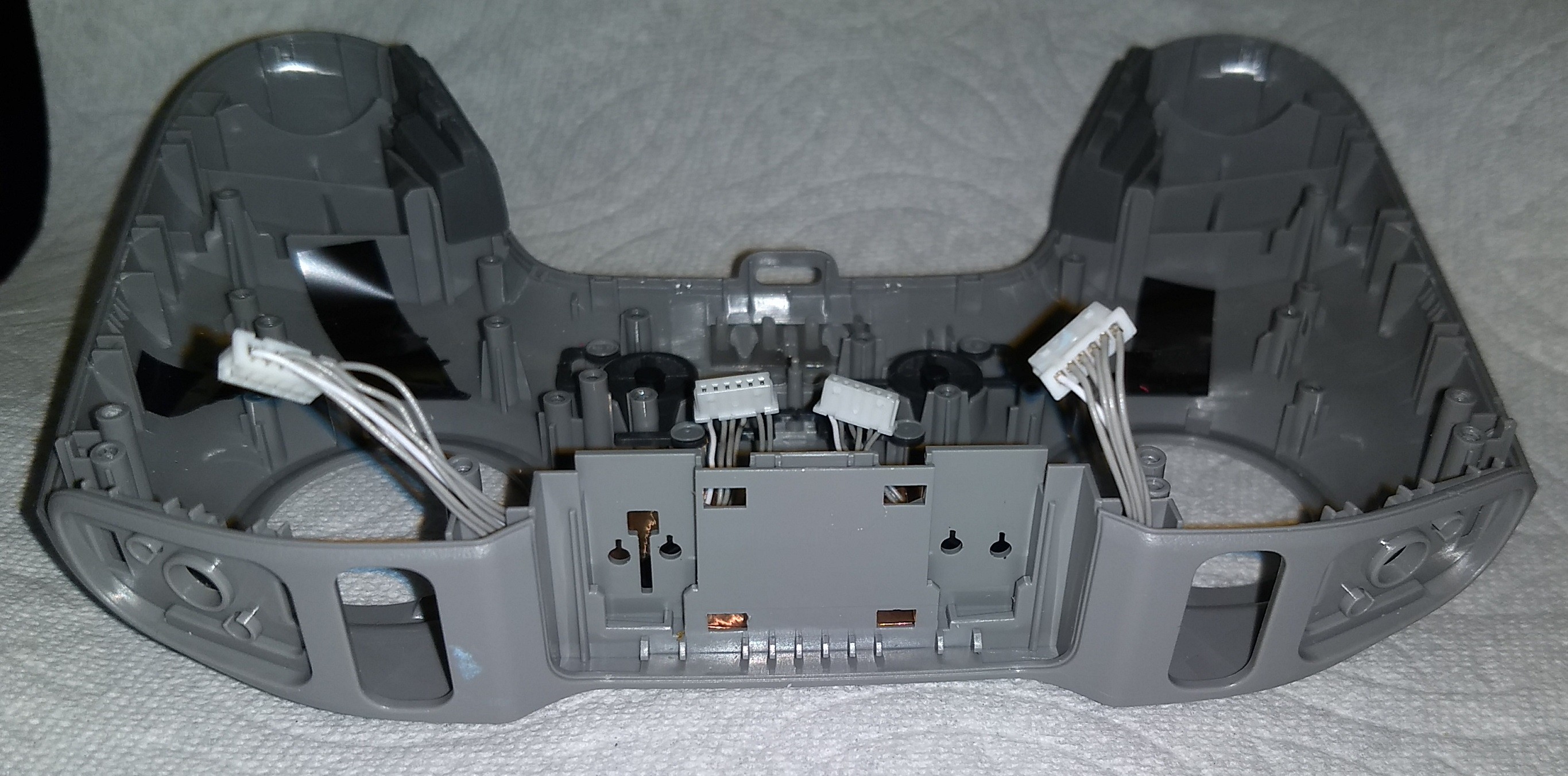
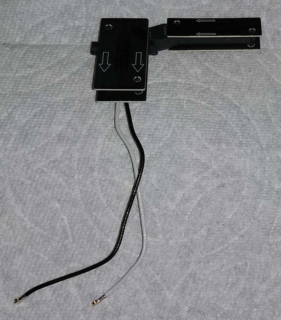
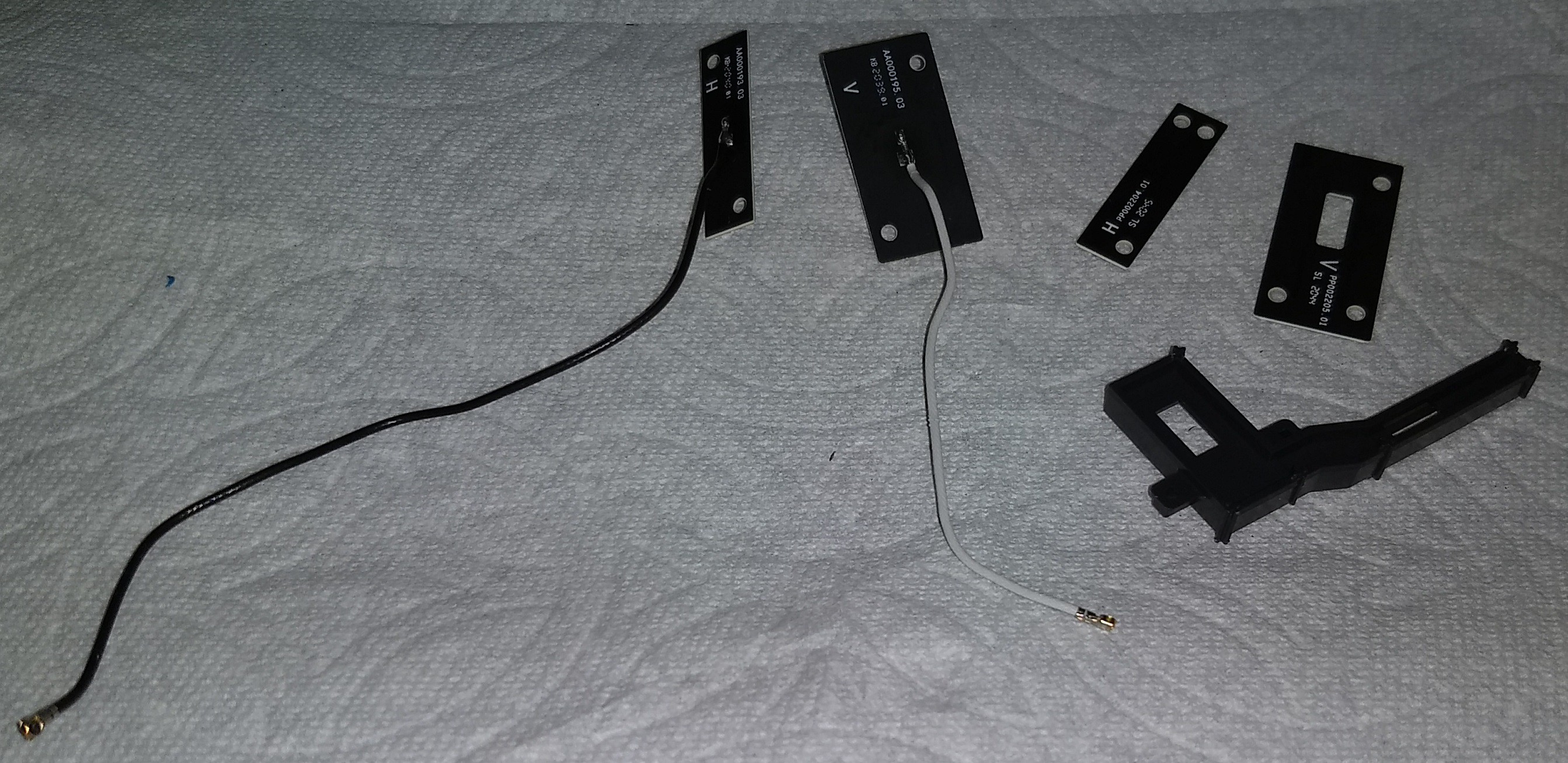
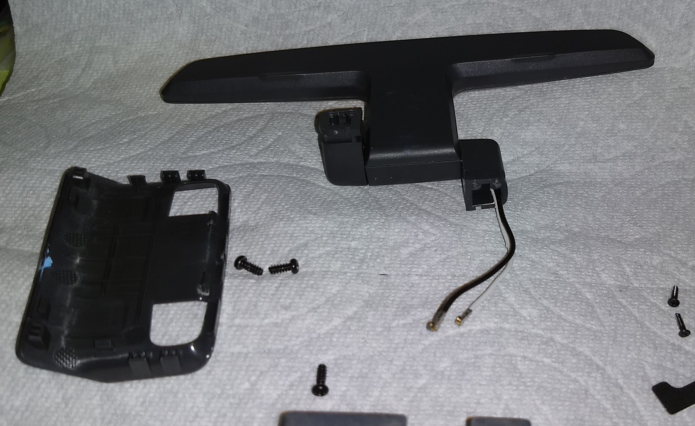 Based on the wires, it's pretty clear this controller has two antennas. I was surprised to see the shape of these antenna.
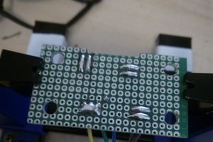
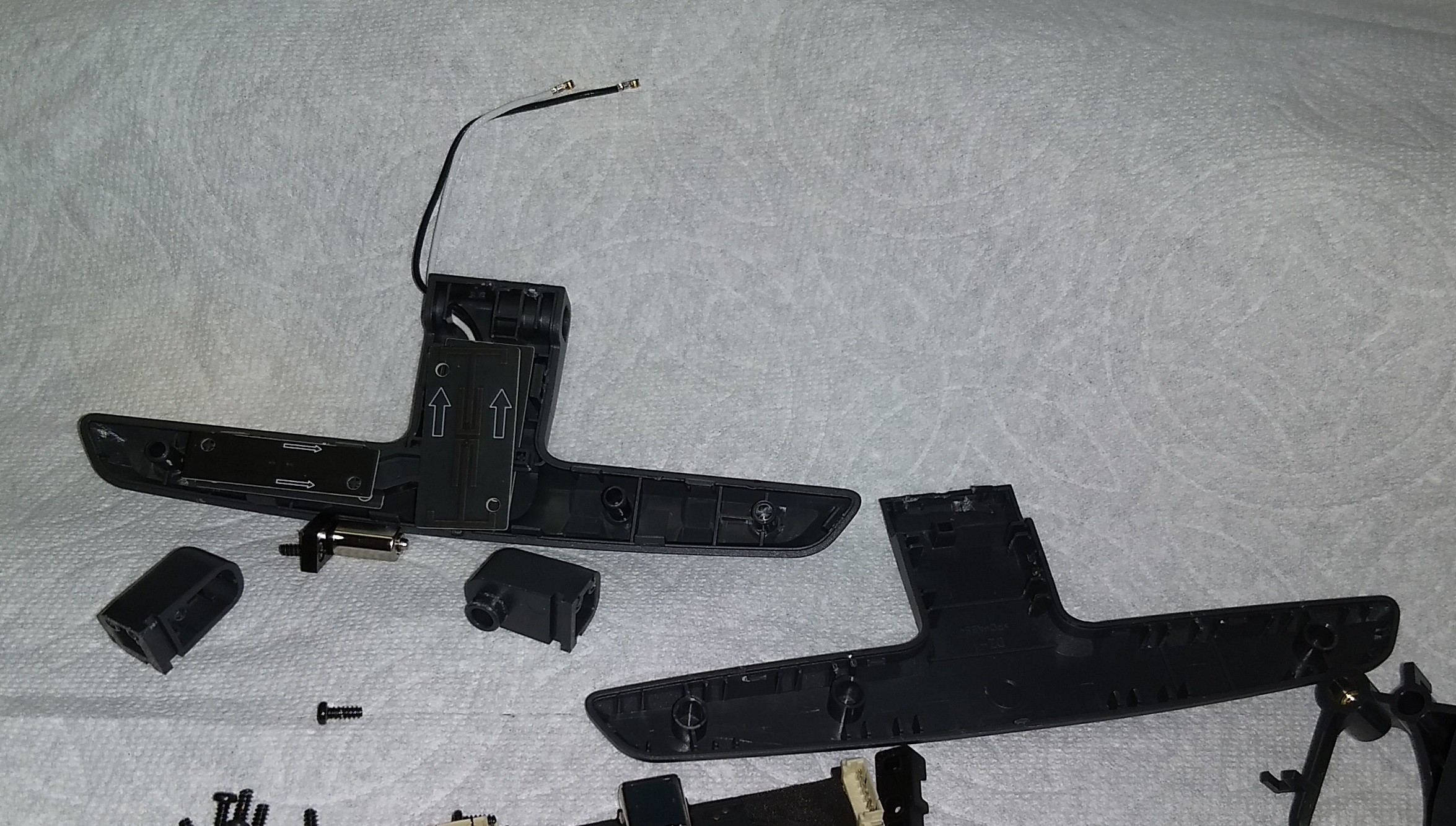


 Andrey Kalmatskiy

 tomcircuit
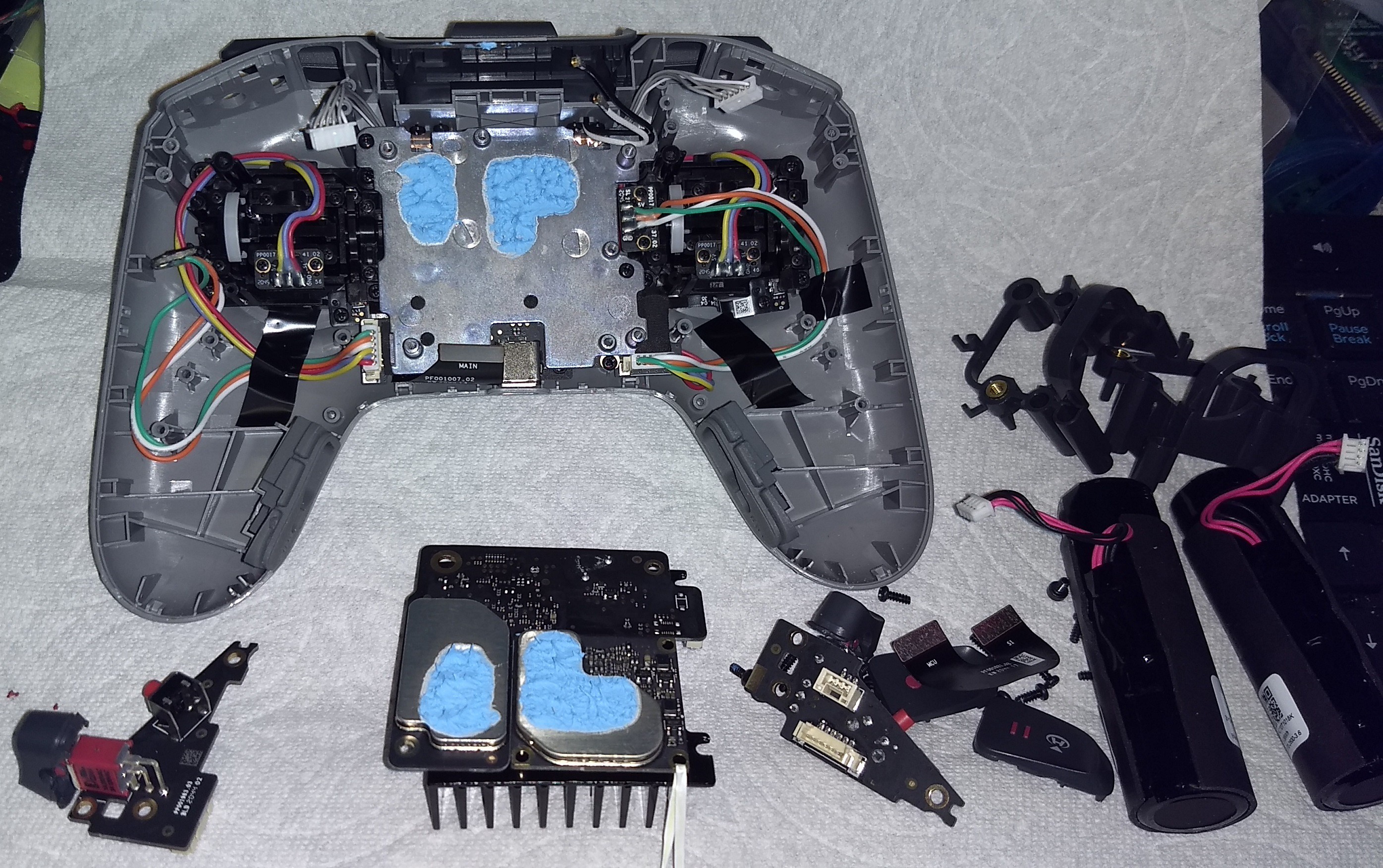
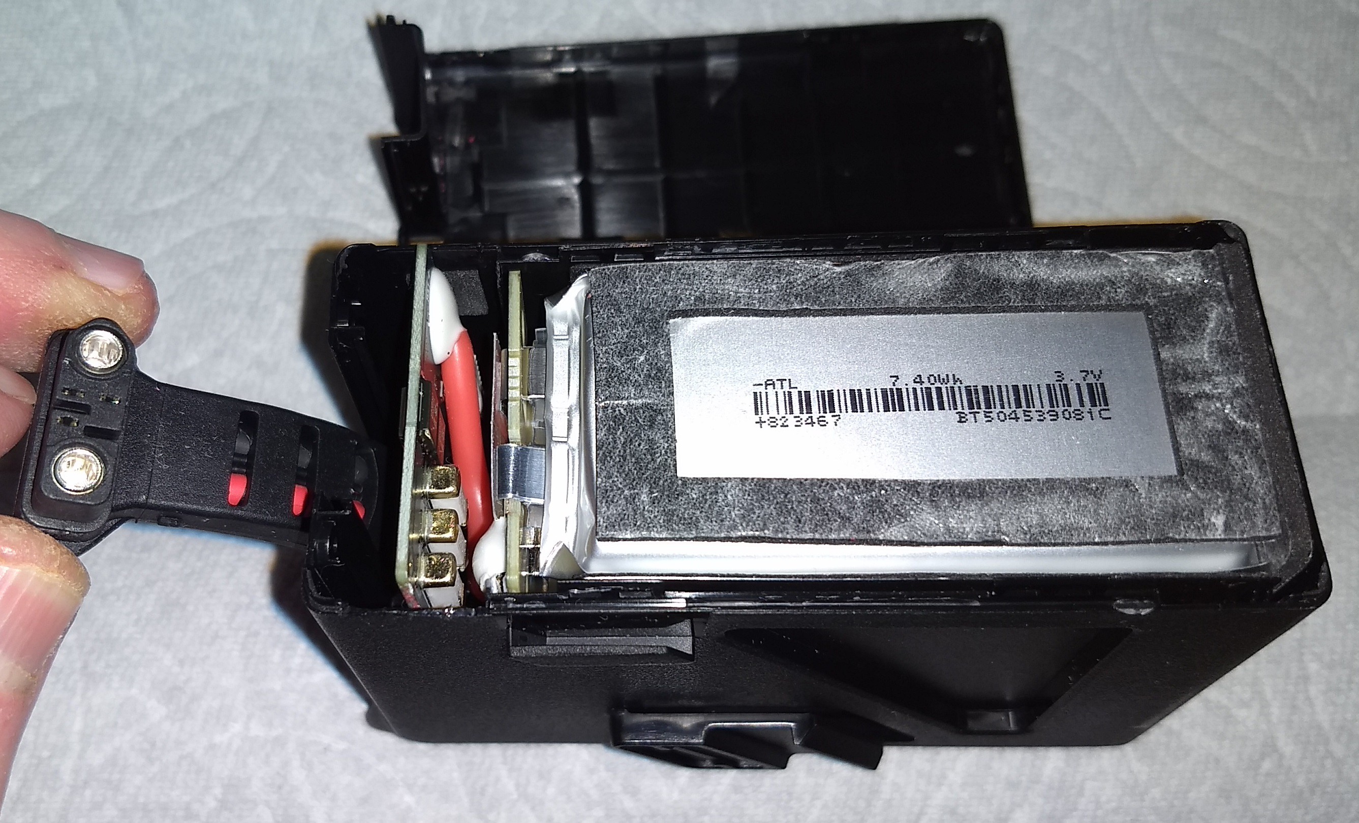
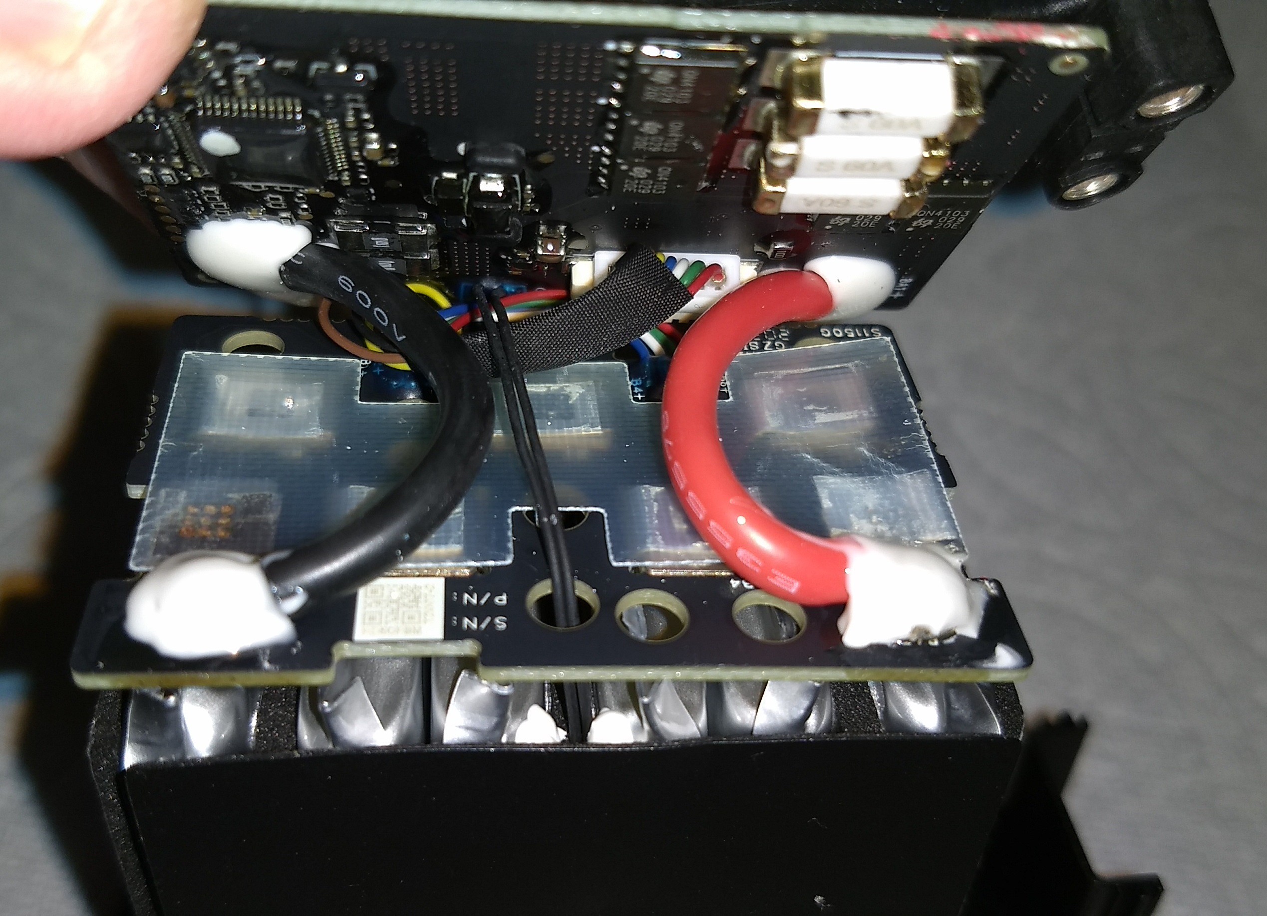
what are dimensions of main battery cells?