 Duane Degn
Here are some photos of the chips inside the controller. As I was cropping the photos I realized they weren't as clear as I had hoped. If anyone more better photos of any of the chips, let me know. I don't promise I'll get better photographs of the chips but a request will make such an event more likely.
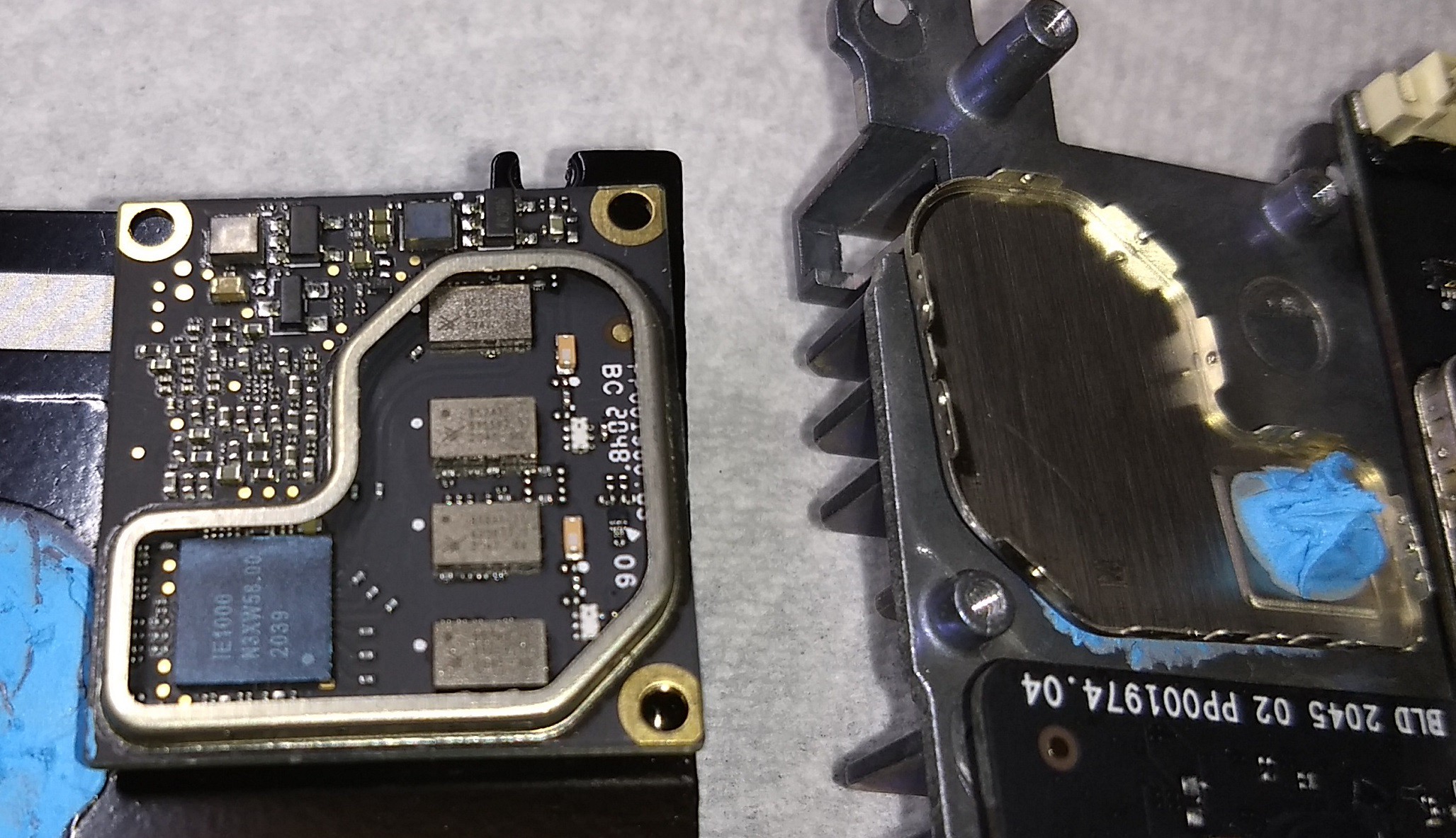
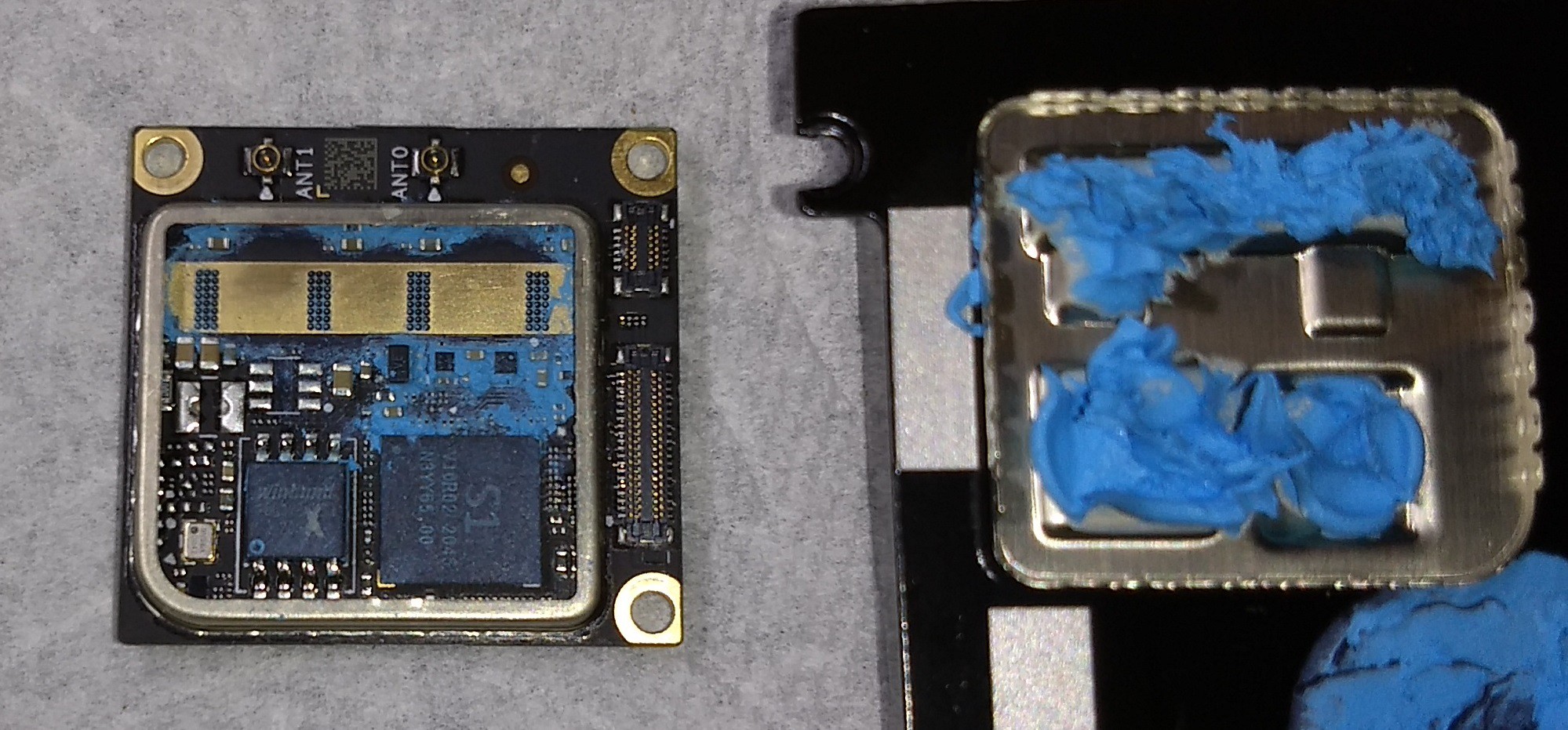
The heart of the controller has two large heatsinks. There's a black one near the back of the controller and bare metal one just behind the top of the controller. Between these heatsinks are two PCB with cans covering portions of the board. Above you can see the top of the smaller square PCB with the can removed. The can also acts as a heat spreader. It was interesting to see the four similar rectangular chips are cooled from the opposite side of the PCB.

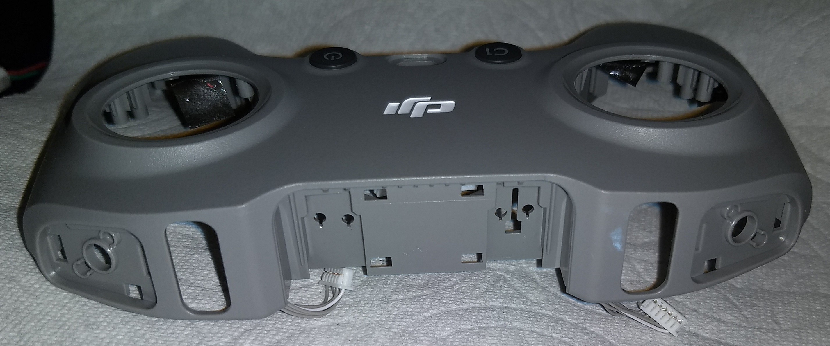
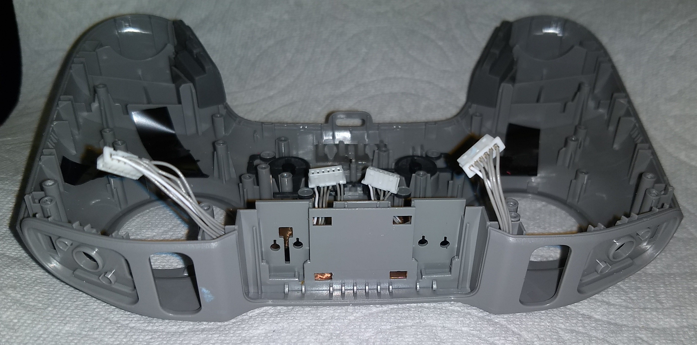
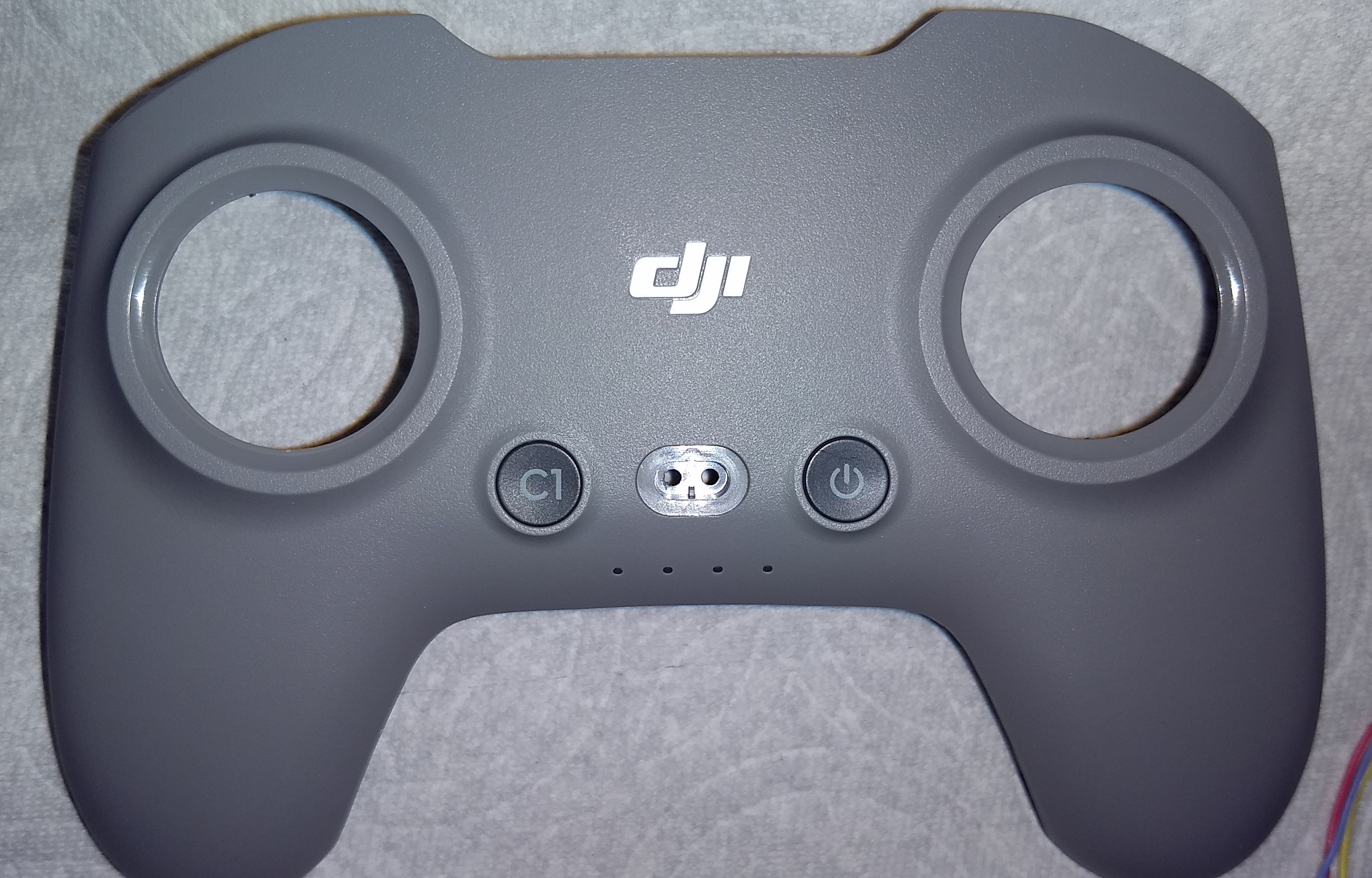
While most of the buttons can be removed from the controller, the C1 and power buttons have plastic attachment points which have been melted to hold them captive.
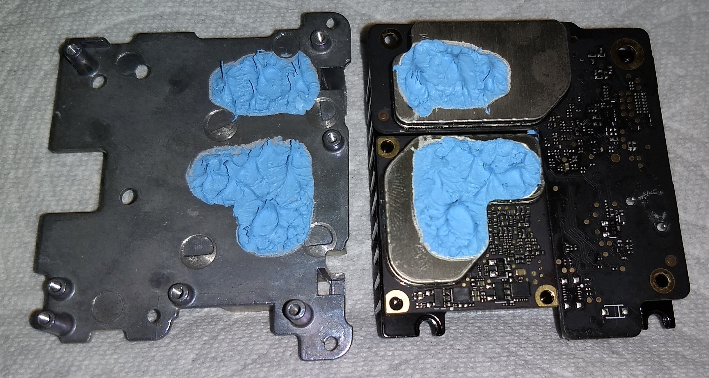
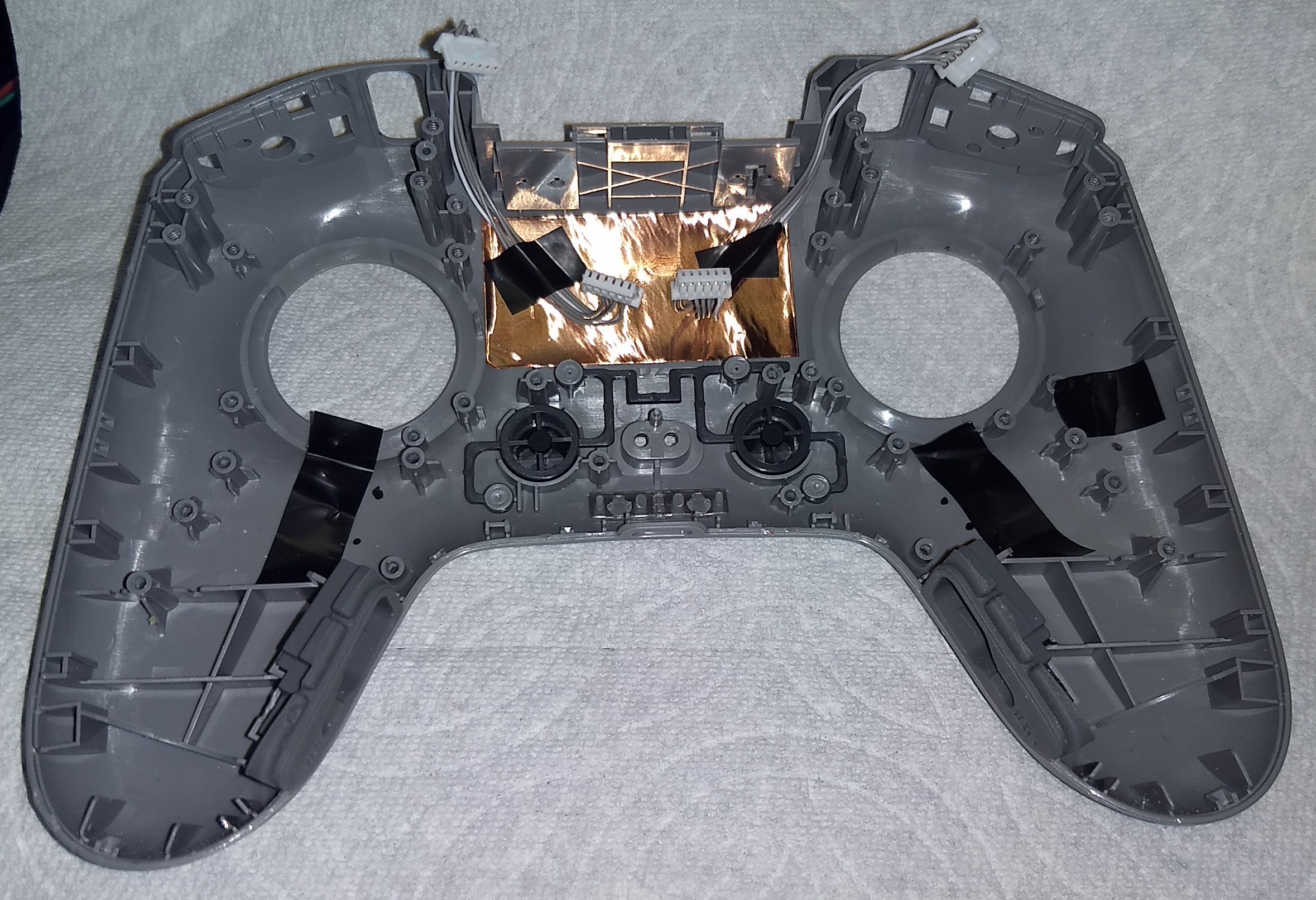
The two wire harnesses seen in this last photo are sandwiched between the copper tape inside the top of the controller and bare metal heatsink.
I have plans to examine more of the components which come with this drone in the near future.
Discussions
Become a Hackaday.io Member
Create an account to leave a comment. Already have an account? Log In.
Very interesting indeed, thank you for taking the time to disassemble and document this!
Are you sure? yes | no
You are welcome.
It's very different than other RC controllers I've taken apart.
Are you sure? yes | no