This project will experiment with the NCO (numerically controlled oscillator) peripheral found in many recent PIC16F chips. The goal is to make a very limited RF sweep generator. In most AM radios, the IF stage is a set of tuned filters with a center frequency of 455kHz. This frequency is just below the AM broadcast band. This is basic superheterodyne radio operation. The tuned filter bandwidth is normally about 15kHz to 20 kHz wide or twice the audio bandwidth. Old radios need adjustment to get reasonable performance from the tuned stages.
The project will generate a RF signal that quickly sweeps from 400-500kHz. An oscilloscope can be used to plot amplitude versus frequency. This plot is the frequency response of the IF filter stages. In practice, the tuning adjustments interact. There is some practice and art to align and peak the filter stages. Most vacuum tube (AA5) radios have 4 IF tuning adjustments.
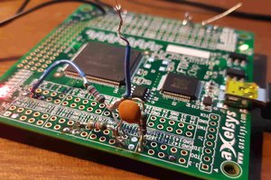
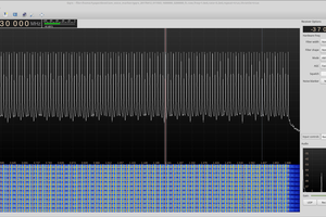
The PIC16F18345 was selected because it has the NCO peripheral and a high internal clock frequency, 32MHz max. The PIC16F18345 was also available on a development board with a USB port for programming. The frequency output from a micro is always the peripheral clock divided by some integer. Unfortunately 32MHz/455kHz isn't an integer. The NCO peripheral dithers between the 2 closest integer divisors to generate an accurate AVERAGE frequency at a non-integral value. The period of a cycle is still based on the integer divider. The average over many periods will be accurate. The NCO peripheral is injecting frequency domain noise to generate a "blended" frequency value. This noise will blur the fundamental in an FFT plot. The noise should be low enough to use the signal for testing a filter.
The math says that a narrow band-pass filter (IF stage) will filter out the frequencies outside the band-pass. That's good if the filter is working. It's unknown if this can be used for tuning and repairing filter circuits.
 Ted Yapo
 doctek
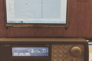
 Dan Kisling