 Wissam Tedros
-
1Servo cable install
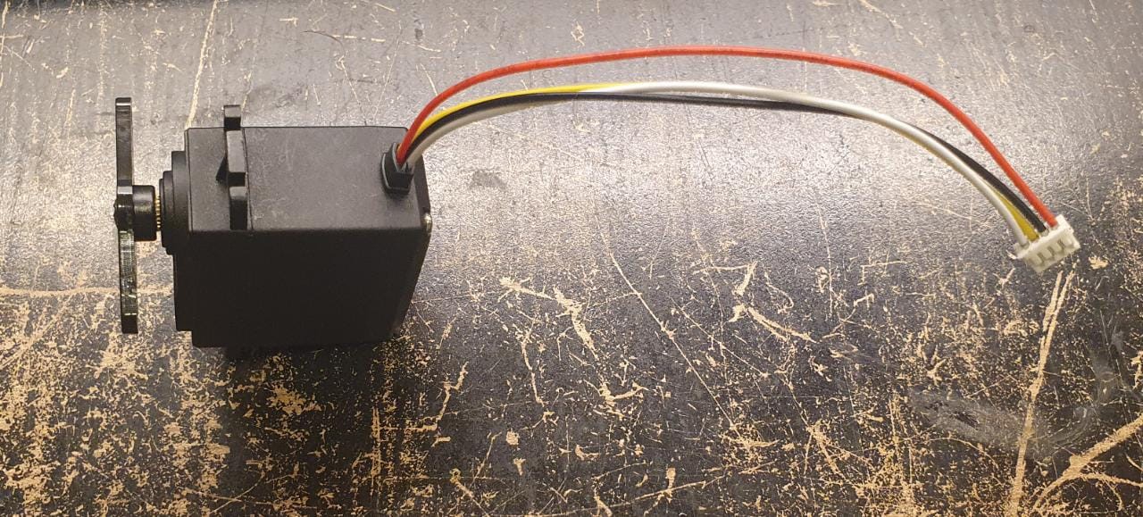
As mentioned in the components sections, you will need to change the cables that come with the servos, seeing that we will need an additional pin to read directly from the servo's potentiometer for position feedback, and since I need to edit the cable for that anyway, I decided to go with a smaller pitch so there's enough space for 12 headers on the board, with the standard 2.54mm pitch header, I may had to go with an overall bigger board, or another breakout board for the servos.
Note that I'm demonstrating this instruction with a weaker servo (13kg.cm) but it still stands for any RC servo
![]()
-Before you remove the back cover screws of the servo, be sure you have a horn on the servo secured with a screw, so the gearbox cover doesn't fall off.
- Now you can remove the back cover screws and remove the plastic cover itself, remove the wire by heating the pads One by one, Do not rip the wire off cold by hand
once removed you can save the wire for a later project, you won't need it For RoDog.
![]()
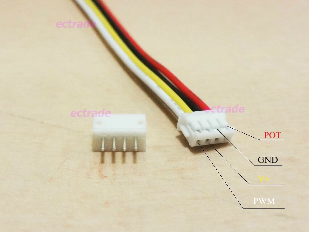
PLEASE DO NOT FOLLOW THE WIRING BASED ON THE COLOURS AS YOURS COULD POTENTIALLY BE DIFFERENT THAN MINE
Before you start soldering on the new cable, insert in the rubber retaining the wires in.
The internal board of your servo should be marked with an "S" on the pad where the signal PWM should be wired to, the middle pad is V+, and the next one is ground, next, you would need to solder the last wire to the middle pad of the potentiometer, and you're done, now do that 11 more times :)
![]()
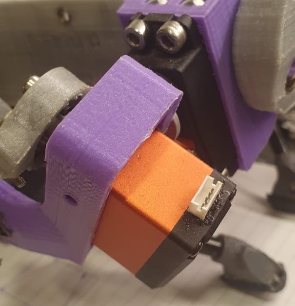
make sure you have a good connection, I would recommend adding some fresh solder on the pads to combine unleaded factory solder with yours, and the rubber retainer is a good strain relief for the cables, you can have a look at the CAD model and estimate how long you want your cable, because some motors are close to the board and having long cables could result in a mess, use the full whole cable length for the knee servos.
I personally went with a header on the servo instead of directly wiring the cable, but it is fairly harder, Would not recommend it. You can do it like that, just double and triple check each pin and probably go with cables that have pins on both ends, directly connected, meaning the first pin on one side goes to the opposing pin directly.
![]()

Discussions
Become a Hackaday.io Member
Create an account to leave a comment. Already have an account? Log In.