 danjovic
The MSX keyboard is arranged as a matrix of up to 11 lines by 8 rows. The lines are selected bay the 4 lsbs on PPI port C (that feeds a BCD-to-Decimal decoder). The rows are read on the port PPI port B.
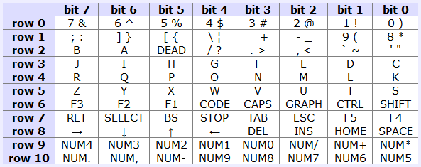
The reading of a given line is made by writing to port C then read on port B.
; register A holds the desired line.
OUT (0AAh),A
IN A,(0A9H)
The technique used on this adapter is to detect a pin change caused by the Z80 OUT instruction and answer in time for the Z80 to sample the data line during the IN instruction.
Z80 Input/Output Timing in MSX
The IN/OUT instruction takes 11 clock cycles. In MSX it takes one extra cycle for M1 cycle:
INSTRUCTION   BYTES   M1         M2        M3
OUT (n),A     2       OCF(4+1)   OD(3)     PW(4)
IN A,(n)      2       OCF(4+1)   OD(3)     PR(4)
During M1 the Z80 fetches the instruction.
During M2 the Z80 fetches the operand in the second byte
During M3, finally, the Z80 reads/writes on the I/O pins.
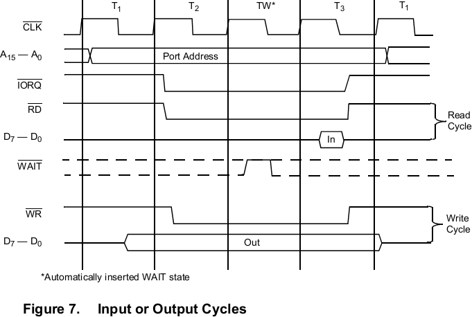
The time interval available to react begins on the half of T2 on the OUT instruction to the half of T4 on the IN instruction, or in numbers:
- 2,5 clock cycles remaining form cycle M3 of OUT instruction
- 5 clock cycles from the M1 cycle of IN instruction ('Opcode Fetch')
- 3 clock cycles from the M2 cycle ('Operand Data' fetch )
- 3 clock cycles from the M3 cycle ('Data Read') as data should be ready to be sample on the middle of T3
Doing the math, we have 13,5 cycles which on a Z80 machine running at 3.58MHz is the equivalent of 3,77us