The goal was to made "something" simple enough to be made from scratch (or, at least, designed from scratch and then having some PCBs ordered online) so I wrote two different sets of dices and then flashed it into a couple of attiny85's:
- d1ce is a single d6 dice that uses 7 leds to show each dot. A standard 8-bit shifter is used to control the different sides
- dic3 is a three-dice-pack that uses different led segments to display numeric values up to 99. It uses a max7219 to control the numbers and it allows different sides for each dice (so you can "roll" one d20 and two d8, for example)
Both work in a similar way:
- There's a timer running non-stop incrementing a seed value that it's used as a seed for the random functions
- On each "roll" the seed is changed to the current seed value and a random value (or values) is picked
- A second timer handles the "animation" of a dice rolling (or numbers changing)
- The final value is shown
I'm not sure if the whole "fetch seeds values based on the button pressing delay using timers" thing is the proper way to ensure the pseudorandomness, but as far as I've checked it seems to work fine (we're talking about simple dices so at least it does the trick successfully). I've written a little bit more about this in the code repo readme.
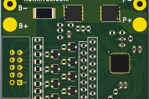
After writing the code and testing it using some protoboards and a bunch of wires I ordered the PCB's.
First I made the d1ce one, which is fully functional but with a small design mistake: the switch holes aren't properly aligned to the right (I used a template intended for a bigger switch).
Then it was the turn of the dic3 board (which also works fine!); but here I made a more important mistake: I added a 3V coin battery holder as the main power supply -like the one in the d1ce board- instead of something around 5V (basically the max7219 requires more than 3V to operate), so unless you wire up the board into a 5V power supply or attach some other batteries the original design won't work at all :_ D
Despite those design bugs (my bad!) the boards were "okay", the wiring was correct and I learned a lot about that KiCad software, the design process, the gerber files and the symbols libraries.
I've uploaded the code for the boards on Github, among with some schematics and the gerbers for the first board. The gerbers for the dic3 one, although, won't be available, since now it's not "fully operative" without a pair of alligator clips attached to my bench power supply :_ D
Changing that battery holder part on the design it's clearly the most important TODO on my list, and I'll probably do it when ordering PCBs for some future project (to save shipping costs, basically). Meanwhile, the proof of concept is finished and now I'm more confident about using these new tools and techniques! : D
 Albert Gonzalez
 Jon Kunkee
 Ben Brown
 Gee Bartlett
 Matias N.