Close
0%
0%

RenixPi

Renix Diagnostics for RaspberryPi

Similar projects worth following

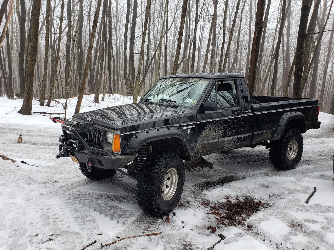
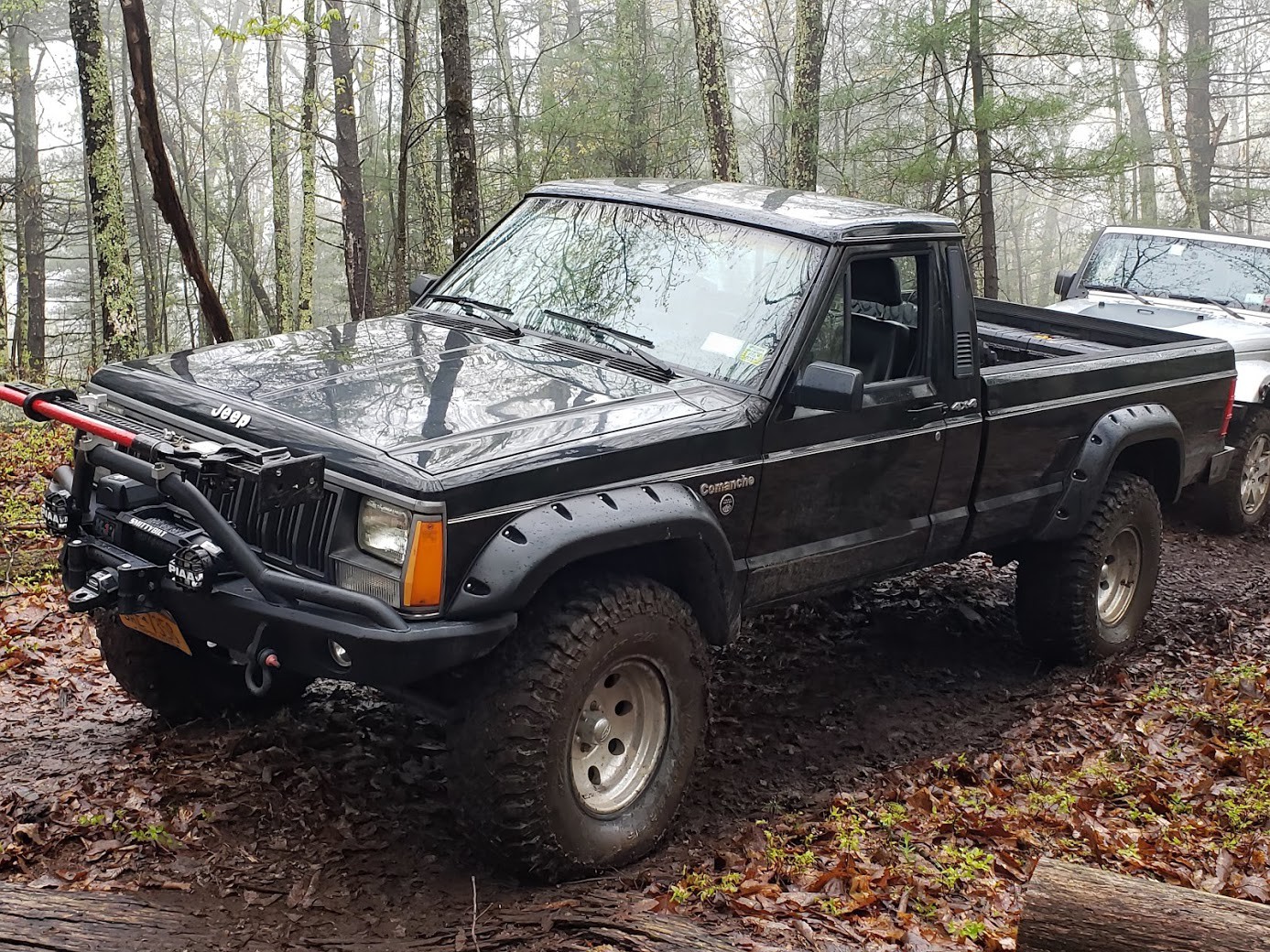
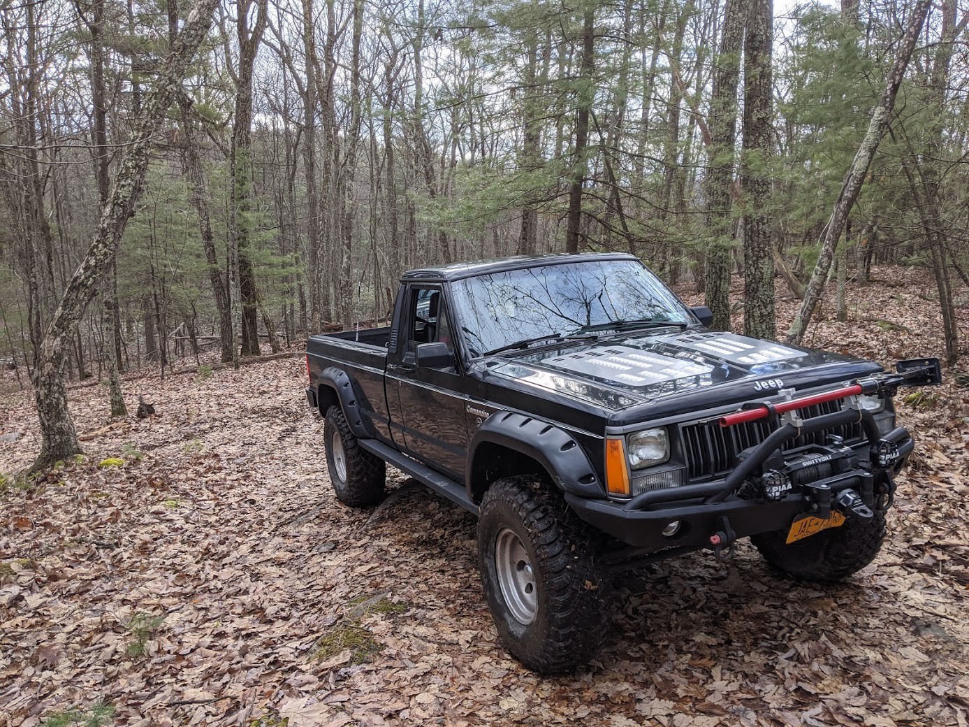
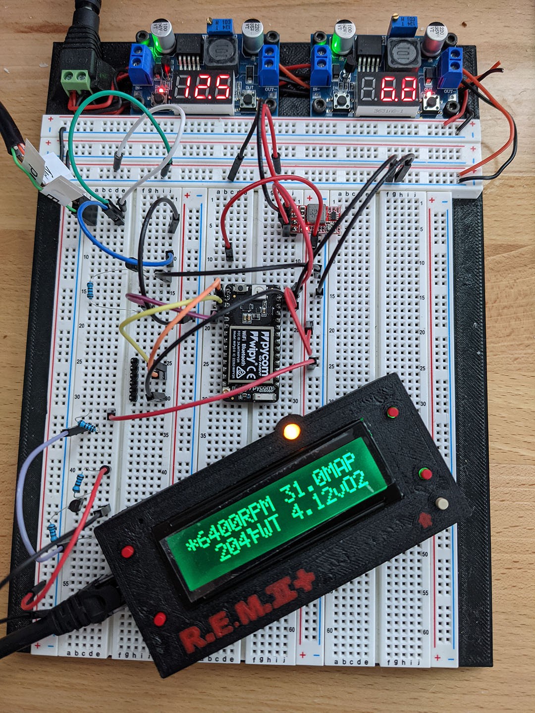
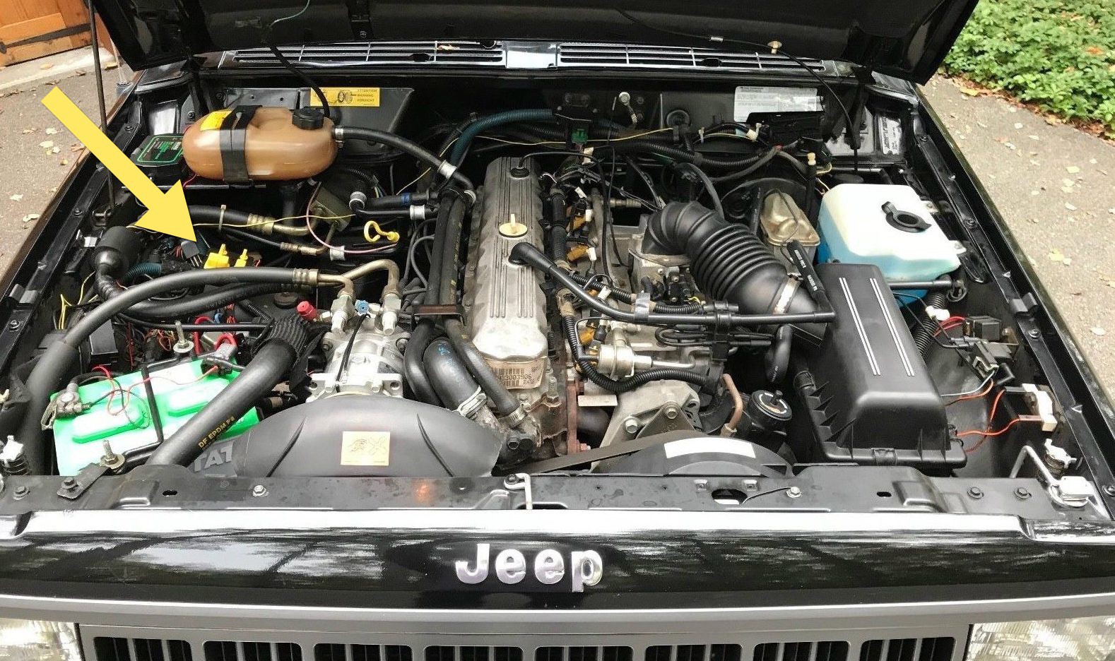
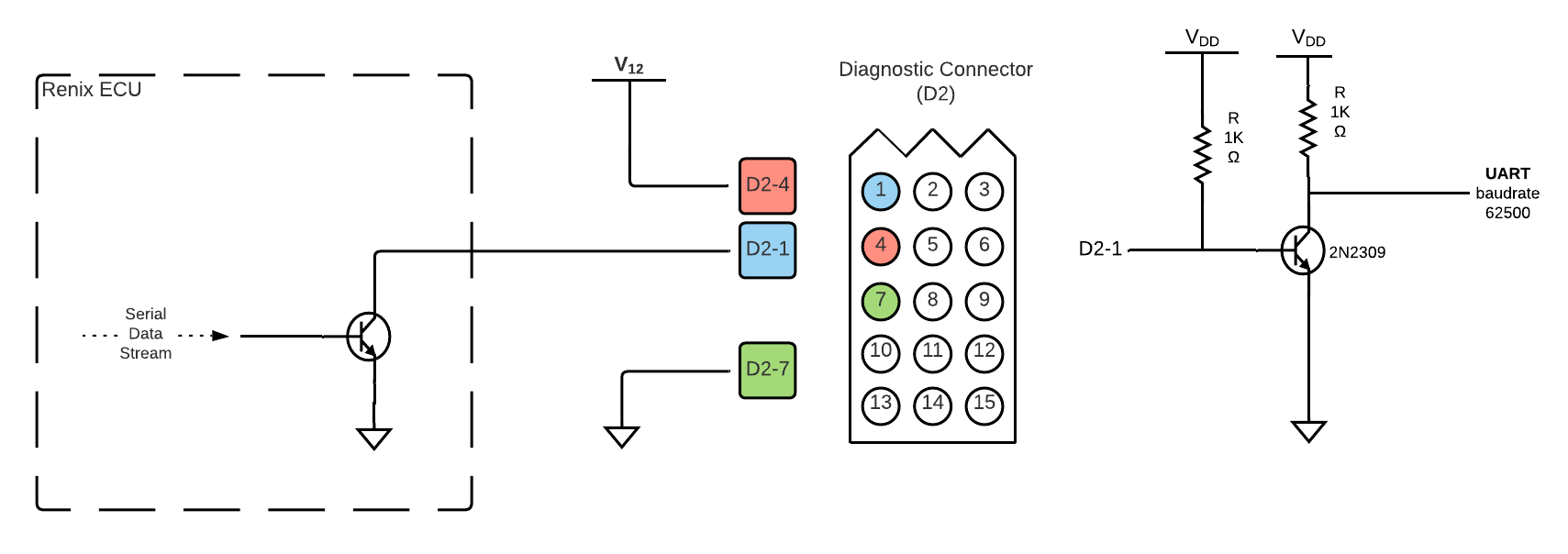
Renault automotive and Bendix aeronautics provided the engine, automatic transmission and anti-lock braking electronics for the Jeep Cherokees (XJ), Comanches (MJ) and Wagoneers (SJ) from 1986 to 1991. Renix (as the join venture was called) had a serial data protocol for system diagnostics that was never published. Thanks to the hard work of Phil Andrews of the RenixPower forum and Nick Grisley of NickInTimeDesign, the protocol was reverse engineered. This project expands on their work to create engine and vehicle diagnostics for my 1988 Comanche, Little Bo' (Jeep).

Additional thanks to my sister, Lauren, for coming up with my Jeep's name.

  • even more TPMS

    PyDrew05/05/2021 at 10:47 0 comments

    A challenge that (most?) TPMS systems avoid is figuring out which wheel has low tire pressure. Keeping track of the pairing of a tire's sensor device id and its installation on the car would go out the window the first time the tires are rotated. Typically, the sensor has a single axis accelerometer to determine if the tire is rotating. One piece of information I came across mentions that if a sensor contained a two-axis accelerometer and was added to the data packet, a TPMS system could determine left from right. And by monitoring the signal strength, determine which sensors were farther away (rear) and which were closer (front). I did come across at least one company who is offering this capability but I haven't been able to determine if that chip ever made it into a TPMS sensor. The manufacturer, NXP, also has a great article on the science & math behind determining roll, pitch and yaw from an accelerometer.

    the microscopic silicon structures that allow accelerometers to sense movement

    A low-power device that spends most of its time sleeping is optimized for sending data creates a challenge in receiving information. And the only situation where the sensor is available for either testing or reprogramming is when it's moving in a difficult to reach, enclosed space. Instead, these devices take a page from the RF ID playbook and can be activated from an external power source: the signal itself being sent to its low-frequency receiver. There is little mention of how this is accomplished other than it operates at a 125kHz. Since the TPMS sensors also send information with changes in pressure, many hackers test by dropping the TPMS sensor into a garden pressure sprayer. With only a few pumps, these can reach a psi of 40 or more.

    In my application, I would happily trade sensor life for a more frequent and consistent rate of pressure readings. Dropping the frequency from every 90 seconds to every 30 might cut the lifespan of a TPMS sensor to 3 or 4 years. But I haven't found a publicly available datasheet which provides enough information on how to build a low-frequency transmitter that could be installed in close proximity to the tire on the vehicle to accomplish this. Yet.

  • TPMS

    PyDrew05/04/2021 at 18:46 0 comments

    With a RaspberryPi installed in my Jeep, expanding the project's capabilities was quite tempting. What other data could I capture? Fuel level? Speed or wheel spin? Tire pressure?

    Tire Pressure.

    As mentioned previously, tire pressure is definitely an important aspect of off-roading. And while mandated on all vehicles in the US since 2008, it was definitely not an option when my MJ was manufactured in 1988.

    When power is discussed relating to wheels, the focus is on the engine and drive line. So I long wondered how TPMS sensors got their electrical power.  I had guessed a self-winding watch mechanism using the tire's rotational energy but, as it turns out,  the sensors simply run on a self-contained battery.

    But this is still a pretty amazing engineering challenge. A sensor has to have wireless communication capabilities (something that is notorious for its power consumption). And be durable as it is subject to rotation and vibration. And light-weight enough not to significantly change a tire's balance when rotating. And be able to operate without requiring replacement as inside a tire isn't the easiest place to service on a regular basis.

    By reducing the frequency of sending data, the solution is a compact device that runs for 10+ years. Data is only transmitted when the tire is rotating and, even then, on an infrequent basis of about every ~90 seconds. In addition, the data packet is very minimal -- only 22 bytes -- which also reduces the time needed for each transmission. Most have just a 4-bit microcontroller.

    One can certainly buy an aftermarket TPMS system. And  some that replace the valve stem cap instead of a sensor inside the tire (although those are just waiting to be lost in the mud some where).

    But where's the fun in that?

    TPMS sensors operate on 433MHz which is a frequency band specifically allocated for low-power devices. And with the advent of software defined radios, receivers for this frequency range are readily available (and cheap); the RTL SDR seems to be the go-to for hackers but others with the same RTL2832U chipset work too. But with no published standard for low-power devices, decoding is a bit of a forensic exercise. Luckily, the open-source project rtl_433 has a community which has worked on collecting a database of devices over the past 6+ years. Including many TPMS sensors.

    These sensors are readily available and range in price. But in light of no standard, there is a proliferation of devices which are not interchangeable between systems. Combining device manufactures, car manufactures and model years creates almost endless variations so picking one that works with rtl_433 is a bit of a challenge. After trying (and returning) several sensors, I decided to splurge on MaxSensors which can be programmed to mimic an impressive list of cars - from a Ford Escort to a Ferrari. It does require a special programming device, but seems that are always 1 or 2 listings for used ones on ebay or mercari at any one time.  And the Gen2 version claims signal strength sufficient for use in 12-ply, 40" tires.

  • a digression into tires

    PyDrew05/04/2021 at 04:18 0 comments

    For those who have been off-roading, the following is probably TLDR; feel free to skip to the next post about TPMS systems.

    Maximizing traction when off-roading is the name of the game. And lowering tire pressure is the easiest of things to improve traction. Dropping the tire pressure allows the tire to "flatten" out, opening the tread pattern (better for dirt and mud) as well as increasing the cross-section contact patch.

    While going from 30 psi to 20 psi doesn't look like much tire deformation, it can nearly double a tire's traction.

    Too low of a tire pressure, however, runs the risk of unseating the tire's bead, the metal wire built into the tire that creates an air-tight seal against the rim ). If this happens, it isn't the end of the world as it's an easy fix even on the trail; jack up the tire, use a ratchet strap to push the bead against the rim and use an air tank or onboard compressor to fill the tire. But it's a pain and definitely brings the entire off-roading convoy to a halt for a good half-hour. On stock rims, I tend to "air down" to 15 psi without much risk of this hassle.

    After-market "bead lock" wheels allow the tire pressure to go even lower by providing an inner seat in addition to the outer one; effectively clamping the outer bead between the rim  (green) and another plate (red) bolted together (yellow). This is a single beadlock configuration as the inner bead does not have a similar attachment; tire pressures can be lowered to 10 psi or lower

    Little Bo is soon getting Hutchinson Rock Monsters with Toyo Open Country Mud Terrain 33s. That is to say double beadlock rims, whereby the beads are held in place against the rim using a hefty 3/4" piece of rubber sandwiched in between two piece rims. (pictures to follow)

  • Powering the Pi

    PyDrew04/14/2021 at 12:12 0 comments

    Tying in a 3A dc-to-dc convertor to the ignition switched power is simple and works great. A manual transmission (especially when crawling over rocks) increases the risk of rebooting unexpectedly when the engine stalls and needs restarting. And while there are reports of corrupted SD cards due to reboots, mine seems to not care that it gets shut off and on and off and on.

    I've explored a few different other options and here are my thoughts...

    • Tapping into power not switched by the ignition and adding a power switch just for the PI is straightforward.  Even if accidentally left on for a day or two, the RaspberryPi isn't likely to drain the battery completely. The battery, when it was installed, is rated at 40Ah; at 12 volts, that's 480 W. At maximum, the Pi consumes 2.5W (500mA @ 5V). Factoring a 50% margin as the battery ages, that's 4 days.
    • Battery-based uninterruptible power supplies (UPS) like PiJuice seem to be cost effective solution for an in-car application. As are super capacitors (low leakage, high capacity) -- such as the Juice4Halt hat -- that allow the Pi to keep running for the few seconds needed between stall and restart or for a graceful shutdown. Either of these off-the-shelf versions seem reasonably priced enough to dissuade me from trying a roll your own solution

    UPS with battery, PiJuice (left); Juice4Halt (right) uses capacitors.
    • Similar to the above hats which run a microcontroller in low power mode to monitor the situation and decide whether to use battery backup or shutdown the Pi, there are some pretty easy software and/or hardware changes to use a standard arduino in this manner. Teensyduino are my favorite which has its own low power library but an off-the-shelf arduino uno/mega has a similar library. Add in some hardware modifications of disabling the power LED and replacing the onboard regulator with a low drop out (LDO) version can drop the power consumption even further. Tutorials can be found here or here. But, as above, there are some pre-built solutions that are hard to pass up since they are also reasonably priced and the hardware lifting has already been done; SleepyPi2 seems to be the best of this breed as it includes all the software utilities and solid documentation.

    While it hasn't arrived yet, I went with the SleepyPi and will share my hands-on thoughts when it does.

  • Form factor

    PyDrew04/14/2021 at 03:44 0 comments

    While my MJ has many upgrades, I do still like the retro aesthetic so it's important to find a place for the RenixPi without it looking totally out of place. The interior of an MJ is minimalistic by today's standards: just a couple of levers for heating/cooling plus a 1-din sized radio. But, even so, the dashboard is bulky and doesn't leave much room for a display where it is easily visible. The space between the gauges and the radio/heater is curiously blank. The panel is styled as if it was intended to display something, although beyond an upshift indicator light (on the mirror panel to the left of the steering wheel) and a small digital clock, it is empty. 

    a "five" indicator panel to the left of the steering wheel (arrow). clock in the top of the right panel (box). the ash tray below (red arrow) is now home to my dual-band VHF/UHF radio.

    While the raspberry pi could be tucked behind the dash, it turns out that the behind the panel is mostly empty space and just large enough for a raspberry pi. While I was able to find a used panel on ebay, a 3D printed version gives more flexibility in the placement and mounting of an lcd screen and the Pi.

    Software updates would be easy by configuring the Pi as an adhoc or access point wireless network, but just in case, I routed usb and micro SD card extensions down so that they're easily reachable underneath the dash.

    The fuse panel is just to the left of the clutch pedal but there is easier access to both switched power via the clock's connections or unswitched by tapping into the cigarette lighter (which I had already replaced with usb charging ports).

  • ECU, M/T vs A/T and ABS

    PyDrew03/29/2021 at 03:46 0 comments

    With all the different variations of the Cherokee, Wagoneer and Comanche, it's no wonder that AMC struggled through the 1980s. The Comanche alone had 9 different trim lines, two different bed lengths (a short at 5' and a long at 8') , two different engine sizes and either a manual or automatic transmission. Add in all the different combinations of the Cherokees and Wagoneers options available, it doesn't seem that AMC believed in economies of scale.

    Renix created electronics that supported both the 2.5 and 4L engines as well as for the automatic transmissions and anti-lock braking systems of that era. Currently, the RenixPi project supports the 4L engine decoding only as the MJs were never offered with ABS and my MJ has a manual transmission.

    If anyone is interested in support for A/T or ABS, please leave a comment. Happy to implement if it's of value to others; otherwise, I'll be focusing on Little Bo' : )

    Little Bo' (Jeep) wheeling in her first spring thaw
    looking oddly clean for the the spring mud of upstate NY
    fall in connecticut, sporting rock sliders to keep the rocker panels safe and a new vented hood to keep the notoriously overheating inline-6 nice and cool
    keeping the frame rust free post-wheeling at a car wash in pennsylvania

  • Reference implementation

    PyDrew03/28/2021 at 15:49 1 comment

    Unfortunately, my Jeep isn't parked near my workbench so using it to test my decode logic (and eventual display) wasn't going to be feasible. And sitting in the driver's seat isn't the most comfortable of development environments.

    Instead, I opted for using a PyCom ESP32 running micropython to create an ECU simulator. And used NickInTimeDesign's Renix Engine Monitor II+ as the reference implementation to verify the accuracy of the simulator.

    PyCom's ESP32 WiPy (center) and the REM II+ bottom.

    And, to simplify development even further, I was able to use the same Python ECU simulator on my Mac to send a byte-stream to a socat created virtual serial port so that it could be used to develop and test the RenixMonitor decoder application without even having to keep a breadboard with jumper wires nearby.

  • Connecting to the Renix ECU

    PyDrew03/28/2021 at 14:18 0 comments

    The physical connector is a standard molex connector with their 0.093" pin configuration. ebay has a pair of plug and receptacle with pins for $10; if you're already placing an order to digikey where you're already paying for shipping, the plug portion is just $2 and pins are 10 cents each. If you prefer, you can print your own with the STLs include in RenixPi on GitHub

    Jeep XJ/MJ diagnostic connectors (yellow arrow) on the passenger's side of the engine bay

    The electrical specification for the Renix ECU is a very common output  of many ICs: open collector to ground (eg I2C). 

    With a pull-up resistor, the (inverted) UART signal can be seen. And along with a transistor and another pull-up resistor, it can be decoded.

    analog output of the ecu with pull-up resistor (top). digital decode after using a transistor to invert (bottom)

  • Renix ECU Serial Data Stream

    PyDrew03/28/2021 at 10:59 0 comments

    The serial data stream that the Renix ECU produces is a 30-byte long frame of data and can be read by any UART interface (arduino, pycom, raspberrypi, etc). To identify the starting sequence, there is a 0xFF marker immediately followed by a 0x00 start.

    Simple enough, except when a measurement is 0x00 or 0xFF. In the former case, a value of zero is only valid if not preceded by a 0xFF marker. And in the latter case, if the measurement value is the maximum value of a byte (ie 0xFF), it must be sent twice.

  • Diagnostic Protocols and a Thank You

    PyDrew03/25/2021 at 17:54 0 comments

    While the On Board Diagnostic (OBD) protocol was established by SAE in 1979, it wasn't until 1994, when California emissions regulations mandated it be included on all vehicles, that it became the industry standard now known as OBD-II.

    Between 1979 and 1994, most companies used some portion of the OBD standard. Renix did not, charting their own path with a proprietary format.

    While some commercially available diagnostic tools were made for mechanics, the protocol was never published. In 2012, a video by Phil Andrews of the RenixPower forum demonstrated his hard work in decoding the protocol.

    Following that, Nick Grisley of NickInTimeDesign started developing the Renix Engine Monitor in 2016 and has been generous to share the source code as an open source project. There are several videos on his website that show the extensive sleuthing that was needed to arrive in his latest iteration. I've purchased one and I've been very impressed, it works great!

    This project is an extension of both Phil and Nick's tremendous efforts and would not have been possible without them.

View all 12 project logs

Enjoy this project?

Share

Discussions

morgan wrote 03/26/2021 at 15:57 point

Fantastic! I also own an '88 MJ! And as the good hacker I am also planned on a similar system. For my first pass I was considering using the Maccina M2 as the primary electrical interface, mostly because I have a couple and they have protected 12v inputs. I like the idea of having a lower power device interfacing with the truck and lighting up 'oh shit' lights, while a more complete HUD can be optionally powered up. Unfortunately I'm facing transmission issues at the moment, so the fun hacking has to wait but hoping this summer to start hacking on the computer.

  Are you sure? yes | no

Dan Maloney wrote 03/25/2021 at 20:33 point

That's so cool, I had a friend who bought a Commanche in 1987 as his first new vehicle. He loved it! Bet your North Idaho vehicle was in great shape -- I've seen cars going back to the mid-70s being used as daily drivers around here. What a difference not salting the roads makes to the life of a car.

Thanks for the info on Renix, I;d never heard of that before.

  Are you sure? yes | no

Similar Projects

Does this project spark your interest?

Become a member to follow this project and never miss any updates