Close
0%
0%

ATTINY_85 Sheild

A shield for working with ATTiny85's

Similar projects worth following
I wanted to create a PCB that would allow me to program an ATTiny85 in about as many ways as I could think of (USB, avrisp, software serial, and arduino as an in system programmer) The idea came from a digispark that I bought and wanted to replicate. I had some AT tiny's that were from a former coworker and decided I would use them for my own projects. Unfortunately they were bricked and I had no way of unbricking them (or so I thought) at the time. So I decided that if I was going to buy some more then I would try and make a project out of working with them that I could try and showcase. My goal was to learn more about MCU's, Programming them, and Hardware design. I also thought that having a shield would come in handy for programming them eventually down the line as well. Hence this idea was born. The board is currently a v1 board and has some improvements to be made but I've already got my V2 board made and on it's way.

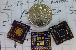
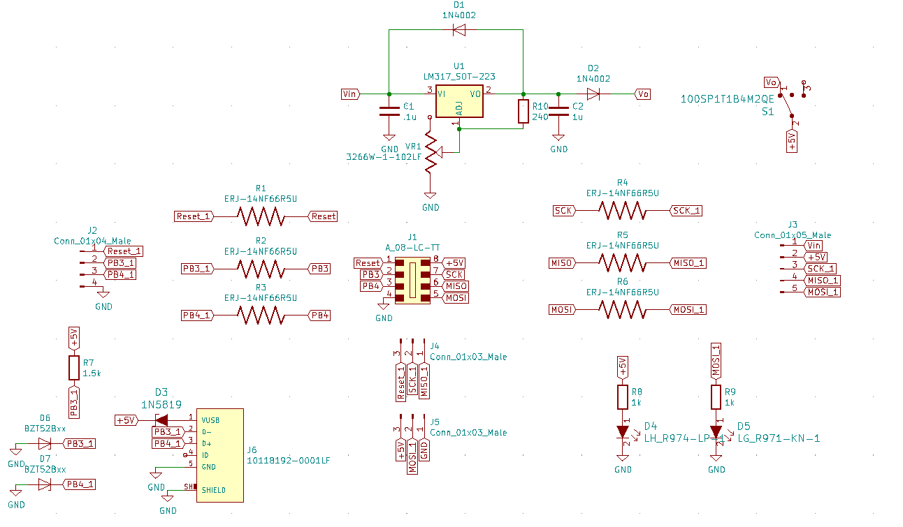
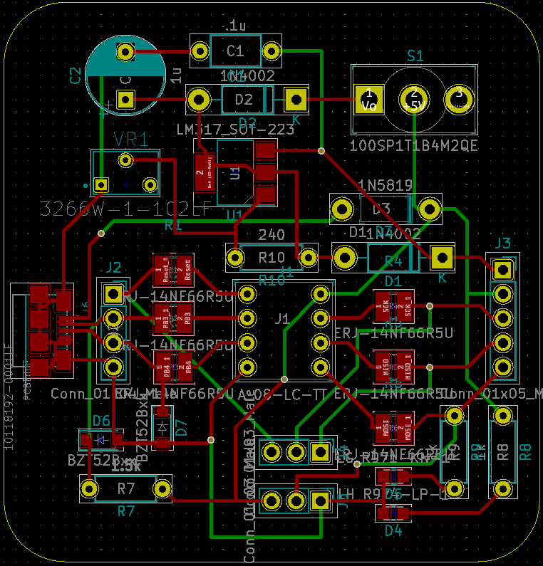
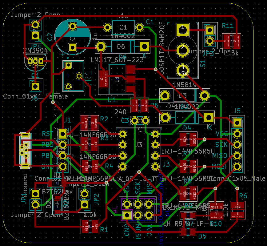
When I started I decided that I wanted to build a board that would allow me as much flexibility with an attiny85 as possible. I used Kicade to create this project. I had worked with the Digispark board that was built with an SMD attiny85 and wanted to be able to include the usb pogramming functionality. I wanted to be able to program the MCU and remove it. I wanted to be able to unbrick it if I messed up the fuse bits. I wanted to make sure it could be powered off of a battery or external power source. I also wanted to know whether it was performing basic functions visually. My initial attempt led me to this design and layout.

Once I received the board and parts I quickly realized that there were some errors made and plenty of room for improvement. The SMD USB connection proved to be too painful to work with and solder on in this situation. I also neglected to label pinouts ( not a big deal but was annoying to keep looking for the proper spots for sck miso and mosi pins). I also liked the idea of using more SMD parts (that weren't micro USB's) because I had more leeway with running traces on the back of the board. 

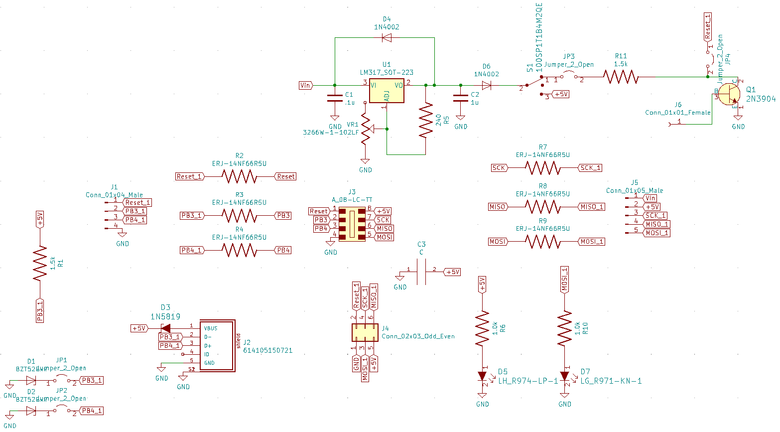
I stopped building this model once I realized it was lacking key functionality that I wanted and decided that instead I would just build a basic board for programming the MCU's and see if I could get a blink sketch to work. This is when I started working on version 2 which became version 3 because of some sloppy file keeping. 

v2/ v3

ATTiny85_BOM.csv

Keep in mind that I have a large stash of headers and female headers and ATTiny85 IC's so these are not included in the BOM. may want to change the 240 Ohm resistor or potentiometer so you can achieve HVSP functionality. Here's a link to the HVSP tutorial I followed. https://arduinodiy.wordpress.com/2015/05/16/high-voltage-programmingunbricking-for-attiny/

ms-excel - 3.84 kB - 04/15/2021 at 18:06

Download

ATTiny_85_Circuit_2.zip

better version. made a copy just in case I caboshed my Gerber files and moved onto V3. Here for archival and showing progress purposes.

x-zip-compressed - 8.48 MB - 04/15/2021 at 17:53

Download

ATTiny 85 Circuit.zip

First attempt at the design. Good start but has some flaws.

x-zip-compressed - 3.86 MB - 04/15/2021 at 17:53

Download

ATTiny_85_Circuit_3.zip

3rd version with better spacing for AVRISP MKII programmer, Better Micro USB then the surface mount one, added jumpers to be able to disconnect the Zenner Diodes from the rest of the board, added capability for on board HVSP (I soldered the wrong resistor value on the board to get to 12V though. Either need to add a higher value Potentiometer or smaller resistor to the feedback line of the linear regulator.) Also added a way to disconnect from the NPN transistor as well as from the rest of the circuit in case the regulator needs to power something else.) Also if you modify the circuit and pull the changes into the board layout editor you will need to modify the pinout for the 2n3904 resistor. For whatever reason the default has the base switched with the collector or emitter pins. (This is from the Digikey kicad library.)

x-zip-compressed - 4.63 MB - 04/15/2021 at 17:53

Download

View all 3 project logs

Enjoy this project?

Share

Discussions

Similar Projects

Does this project spark your interest?

Become a member to follow this project and never miss any updates