 Josh Gadeken
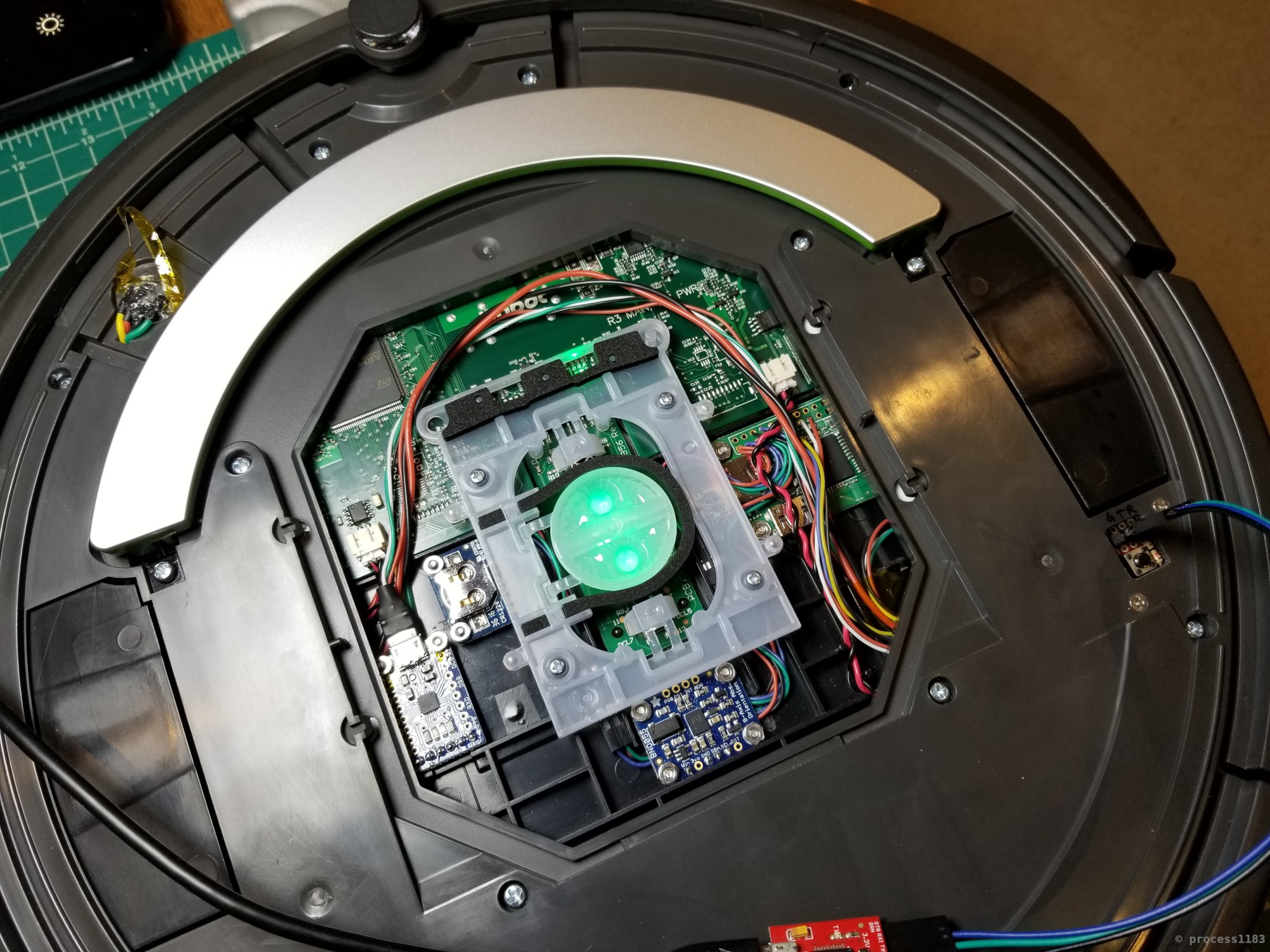
The first step of this project was to disassemble the Roomba to clean it (there was a large amount of dust build up from doing its job.) After cleaning, I needed to see if there was even room in the chassis for the RPi, IMU, and supporting components. There is! I also played around with a few arrangements before settling on the RPi on the Roomba's right side, the IMU in the center behind the button board, and the rest of the components on the Roomba's left.
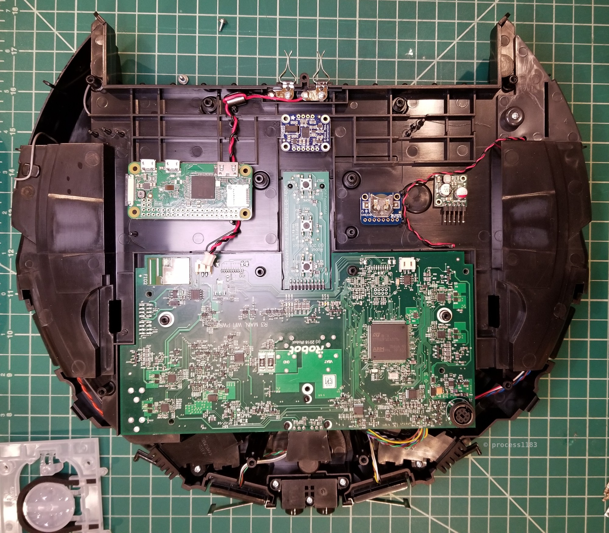
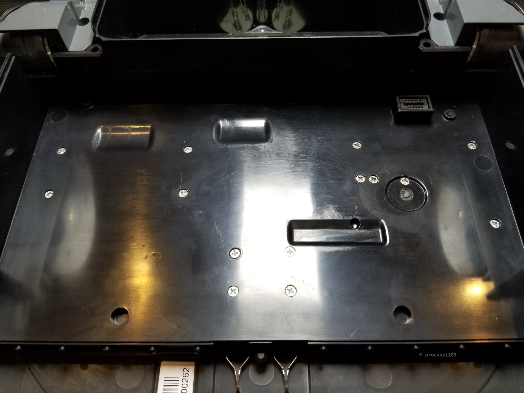
There's just enough room underneath the Roomba's motherboard to run the Open Interface wires from the front of the Roomba to the open space where the additional hardware will be installed.
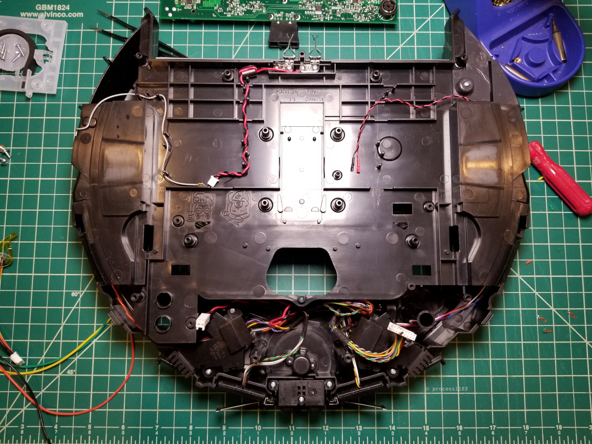
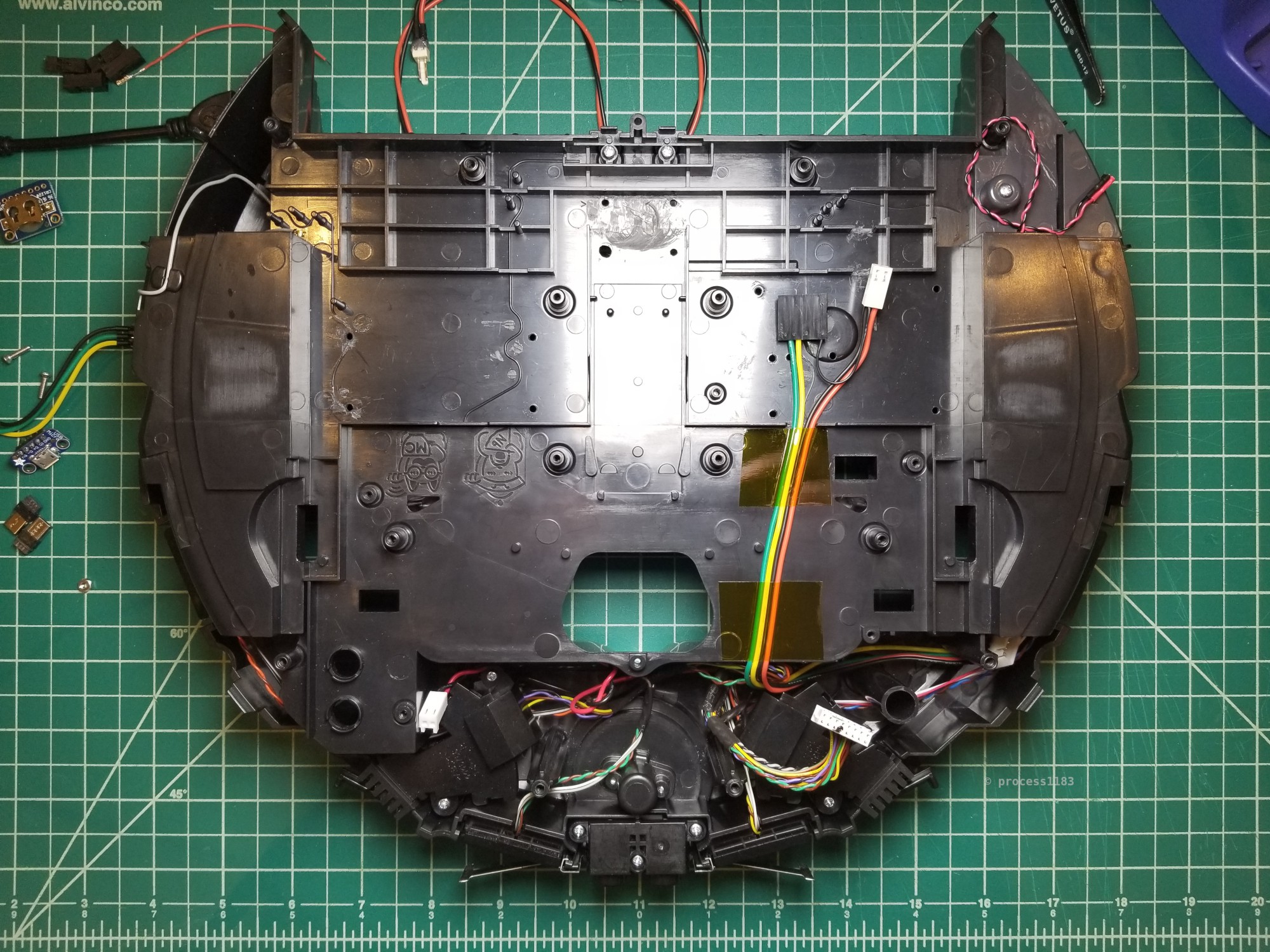
Note: This photo was taken near the end of the build, after the component choices and locations were finalized. This is why all the drill holes are present.
The connection to the USB serial board is nice and compact thanks to right angle headers.
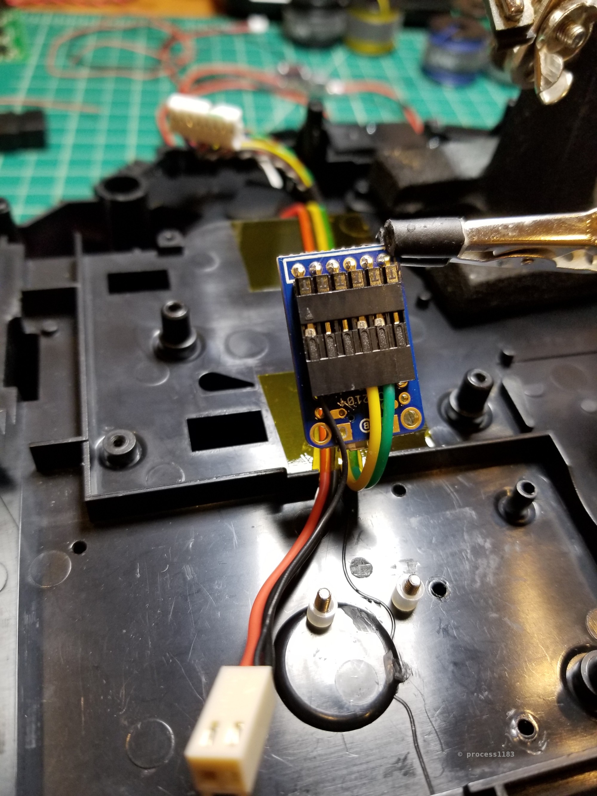
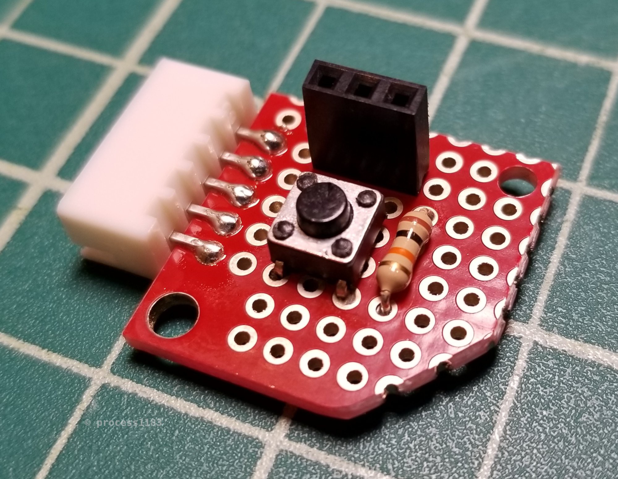
The two I2C connectors and the power button and serial board connector soldered to the Raspberry Pi Zero W.

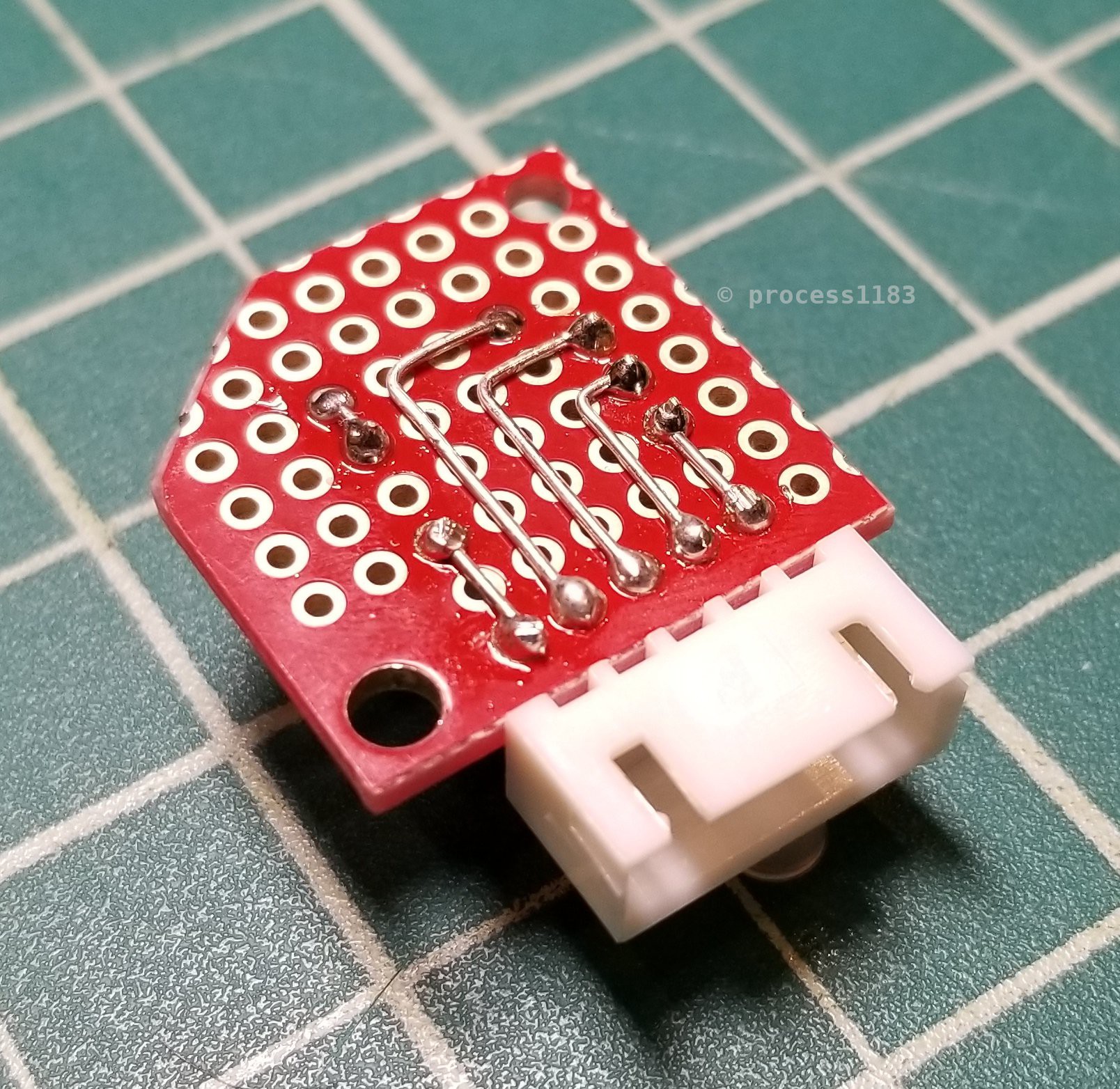
This simple and small PCB makes the RPi's serial port and shutdown button toollessly accessible.
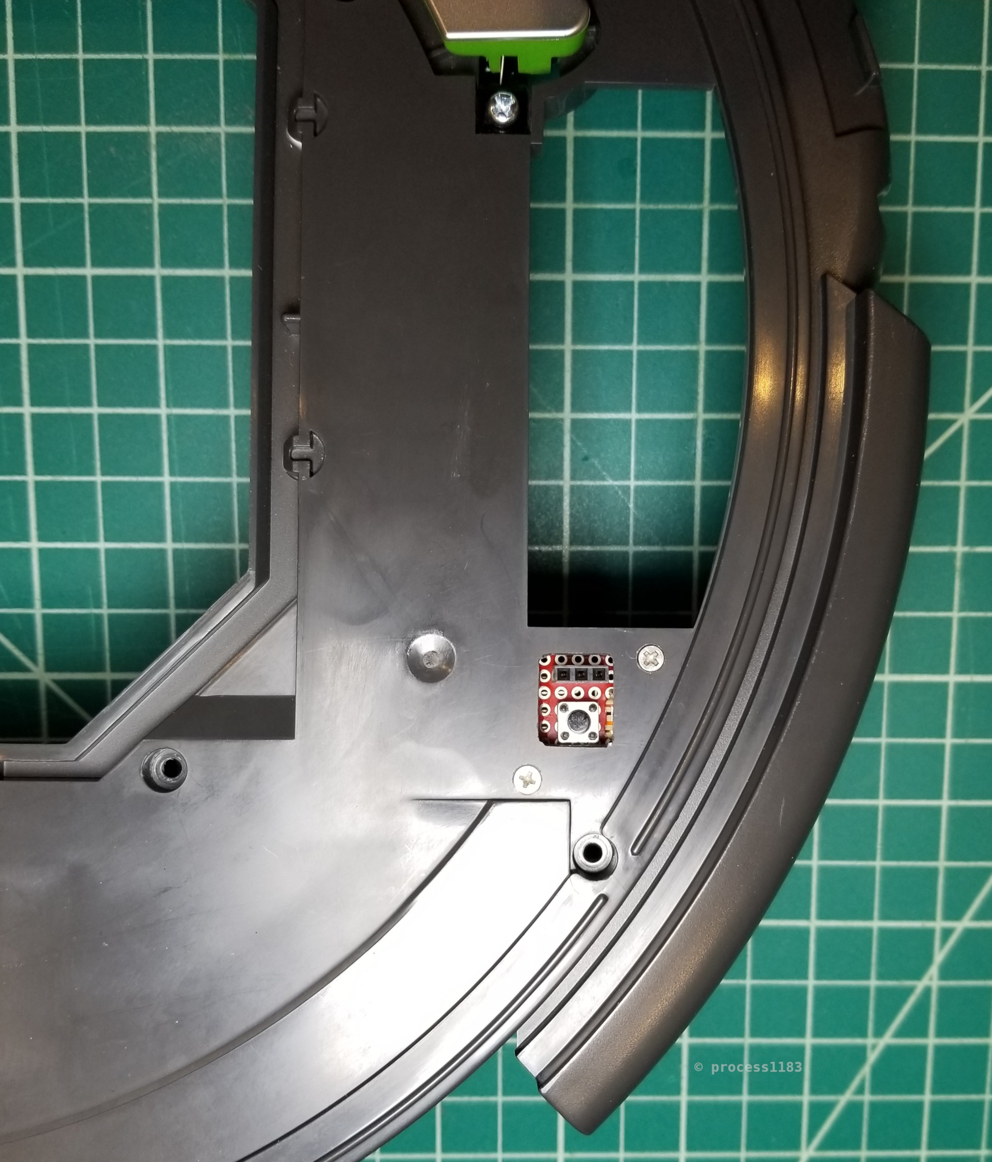
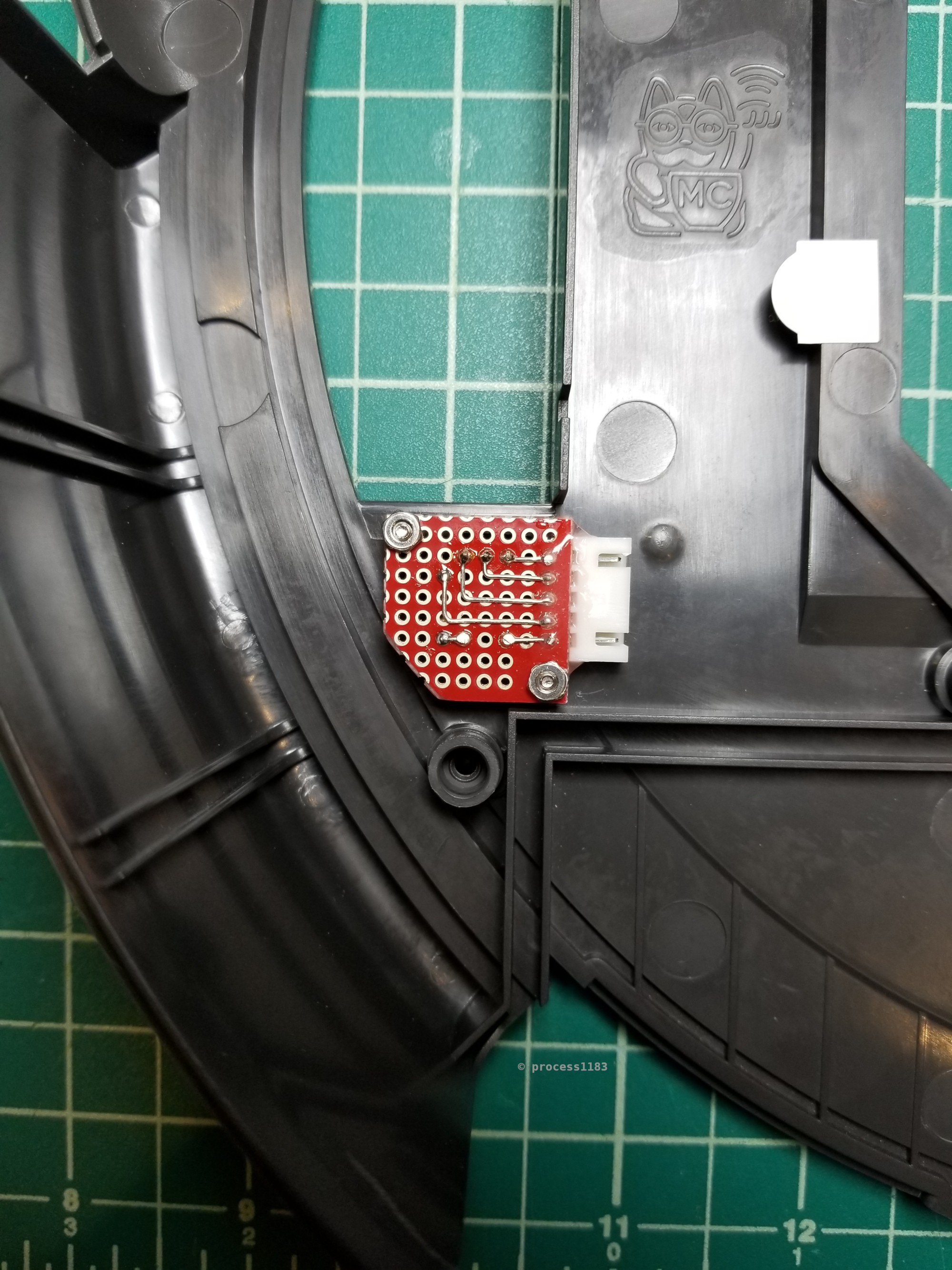
The serial and shutdown button board is installed in the Roomba's top cover behind the right wheel module.
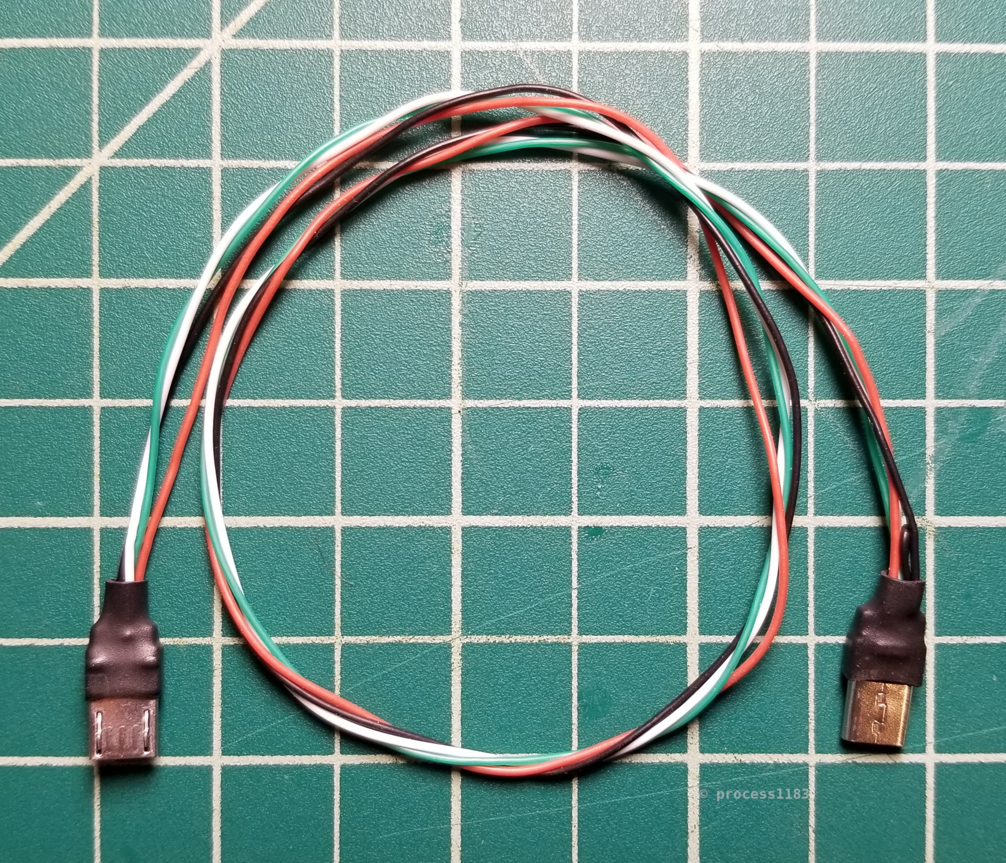
To save on bulk, I soldered a custom micro USB OTG cable to connect the Adafruit CP2104 serial board to the RPi.
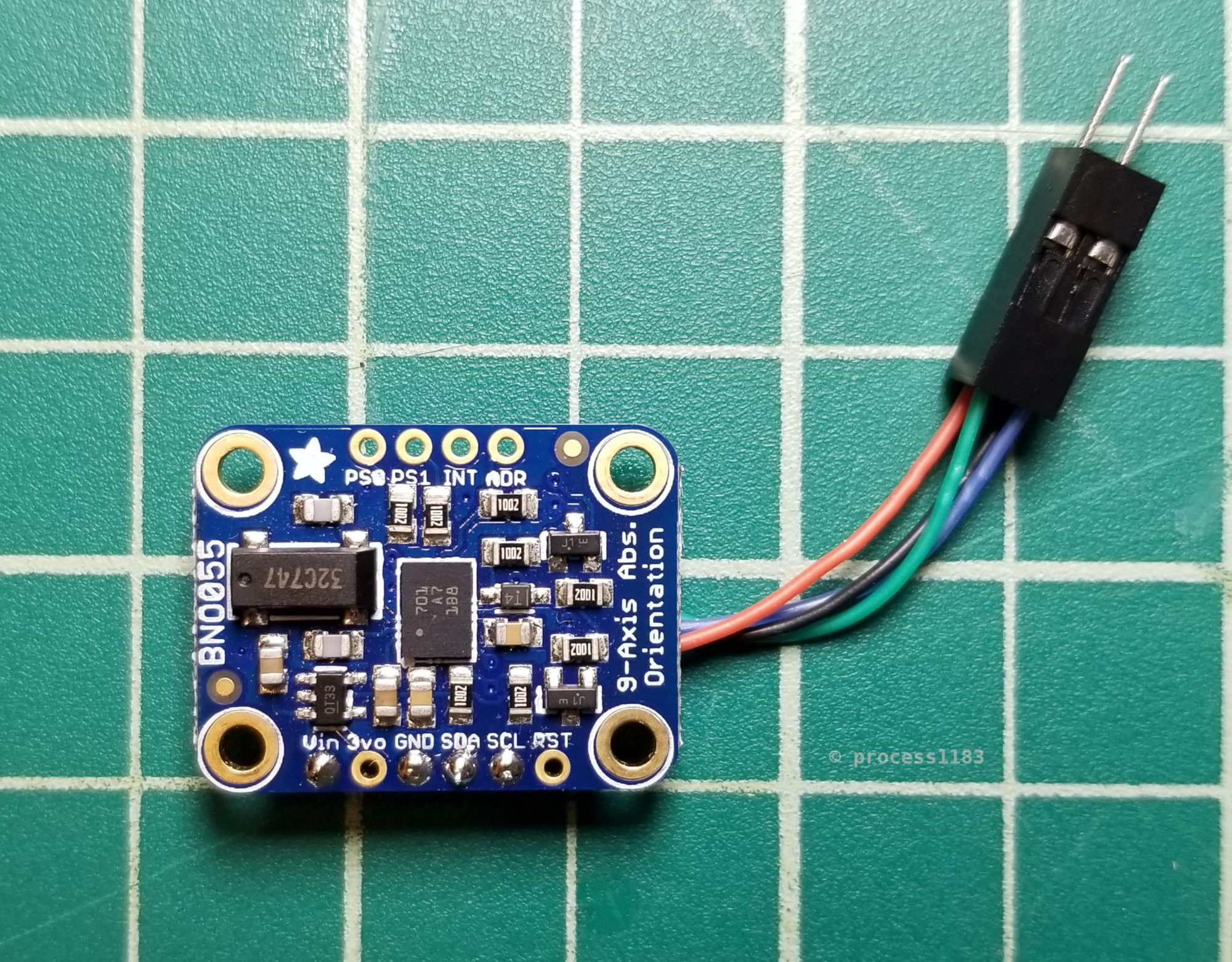
The DS3231 RTC board (not pictured) and the BNO055 IMU board both connect to the RPi through 2x2 connectors.

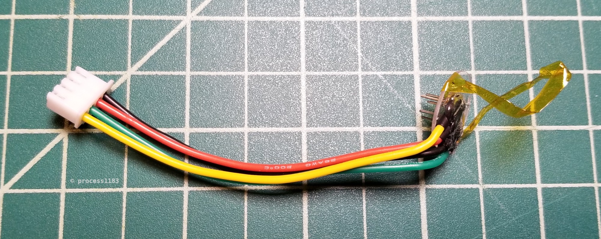
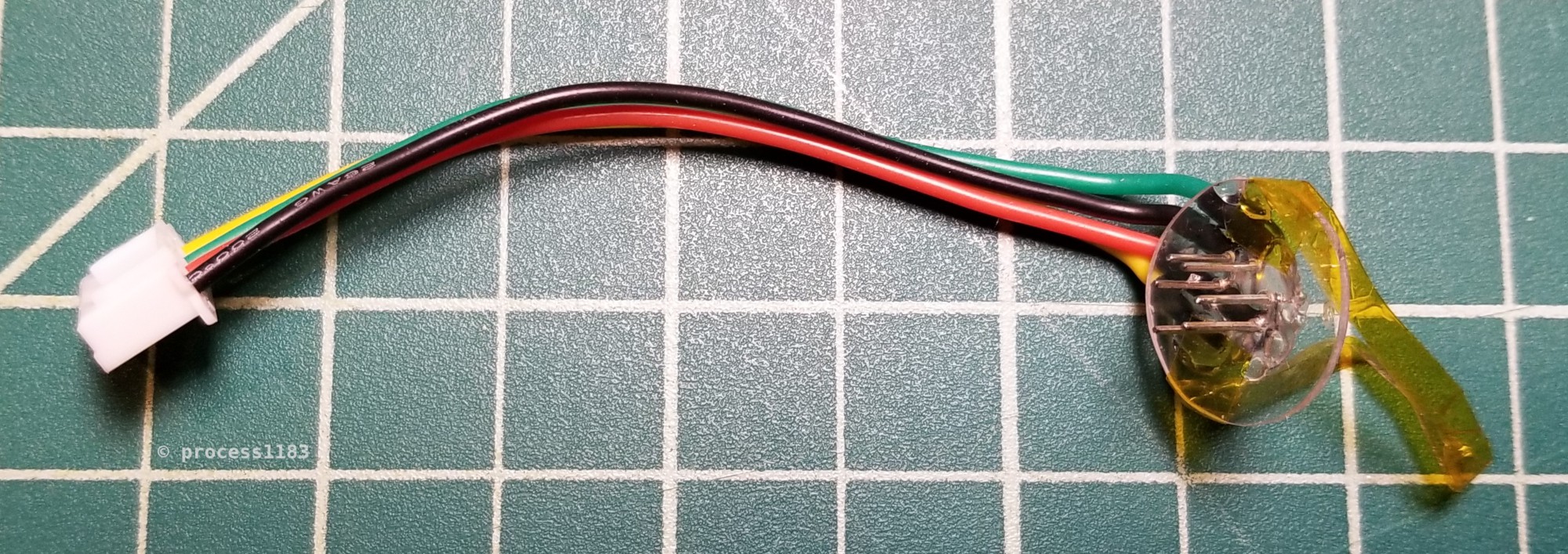
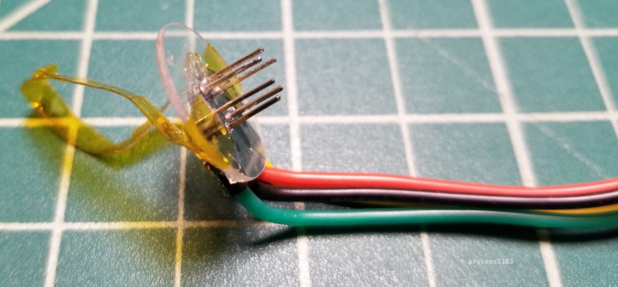
This is the custom low-profile 'mini-DIN 7' connector the I put together after failing to find any comparable existing option. It's janky AF, but it works. To create this, I cut out a small plastic disk that fits right above the Roomba's mini-DIN connector, then marked the pin locations and drilled tiny holes in the disk. Next, I bent some scrap leads into place and soldered the four wires to the 'pins'. In this connector, pins 1 and 2 (Vpwr) are soldered together with the red wire, and pins 6 and 7 (GND) are soldered together with the black wire (pinout is on page 3 of the iRobot Roomba 600 Open Interface Spec). Finally, I added a loop of tape to enable easy removal of the connector. This custom connector does not fit through the Open Interface connector hole in the Roomba's top cover, so it uses an inline JST connector, which does fit through the Open Interface chassis hole.

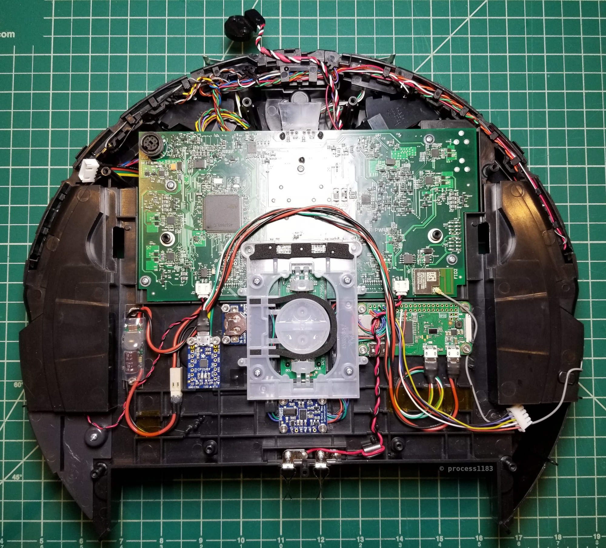
Here's the Roomba with all the additional components installed (minus the serial and power button board on the right).
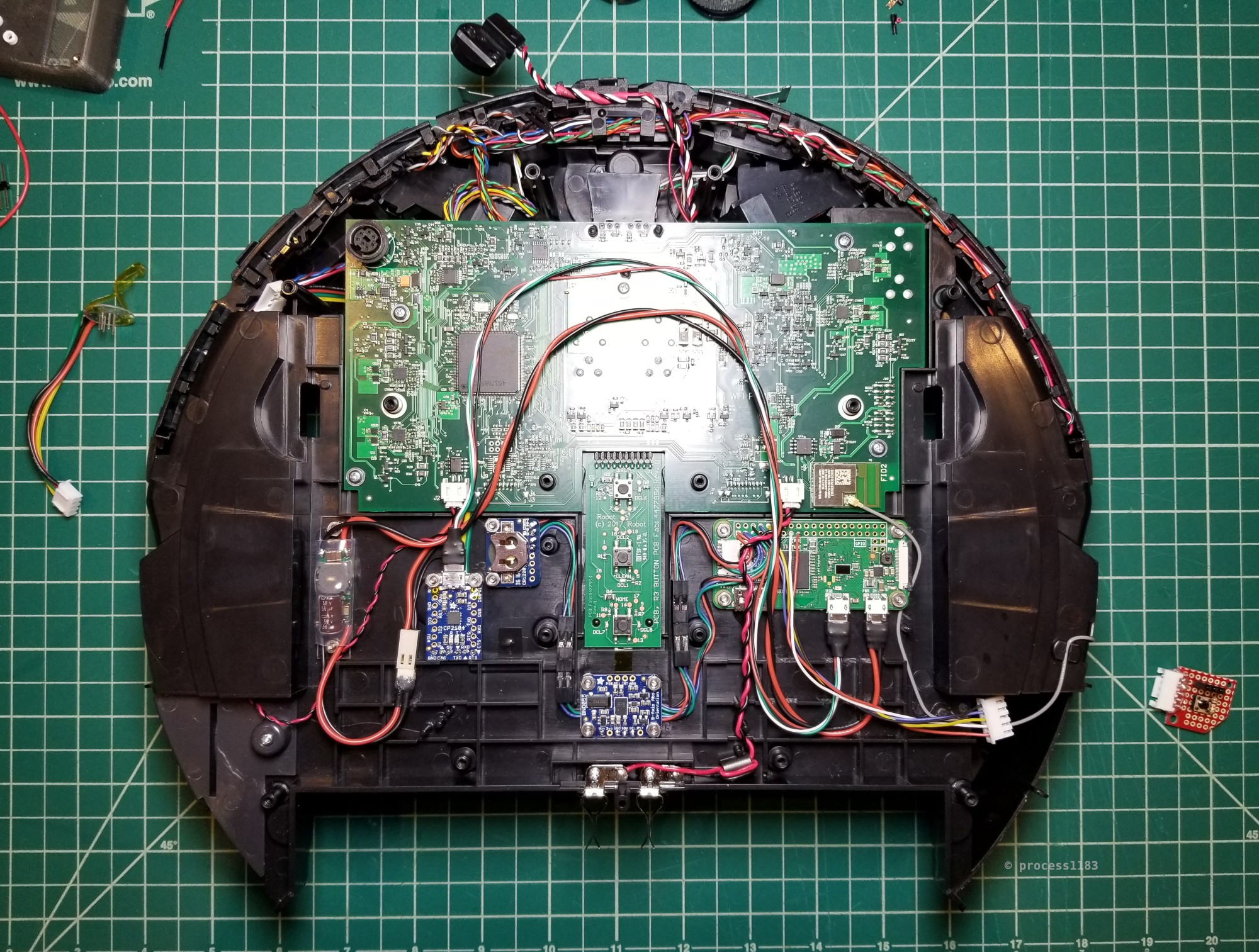
The I2C wiring fits nicely beneath the Roomba's clear button shroud. I also slightly overestimated the required length of the micro USB OTG cable, which is why it needed to be coiled behind the RPi.
All of the machine screws that I used were countersunk into the plastic chassis. The countersinking was required because there's no extra room between the brush module and the chassis.
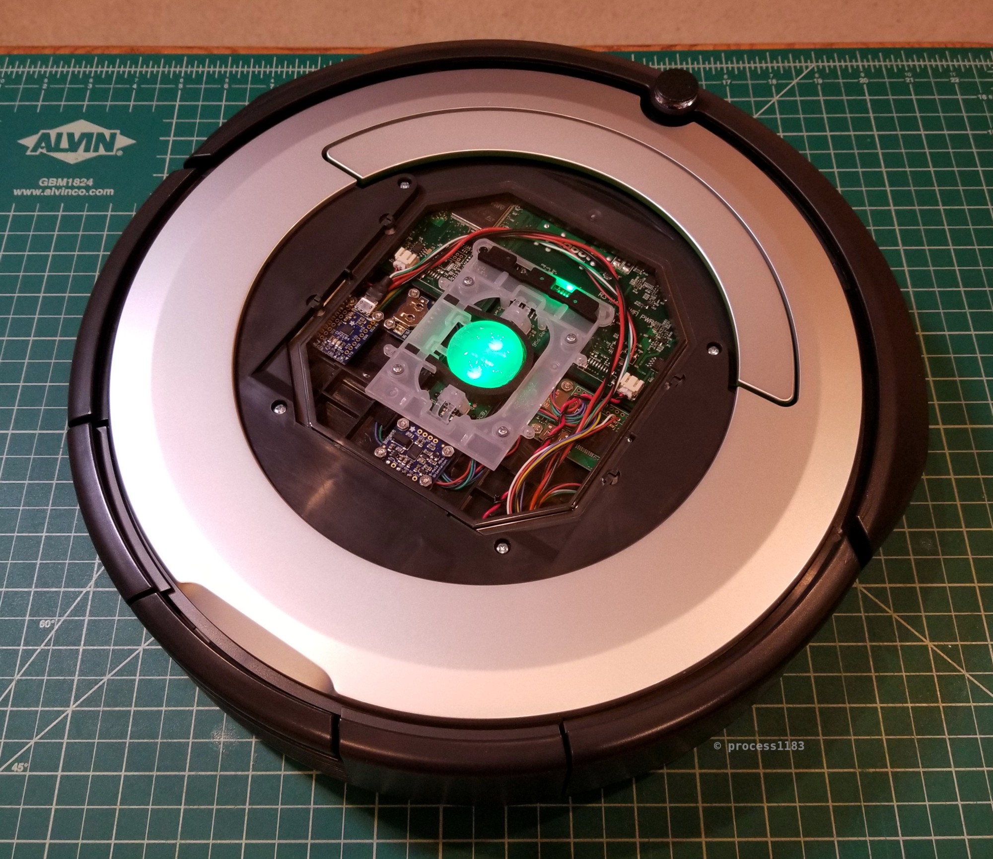
With the Roomba almost fully reassembled, you can see that the Open Interface connector, serial and shutdown button board, and most of the new components can be easily accessed.
The two plastic top covers snap into place. The outer silver plastic ring that conceals the Open Interface connector and RPi's serial port and shutdown button is trivially removed by hand. The center black logo and button cover is a little more difficult to remove, but can be done with a plastic spudger.
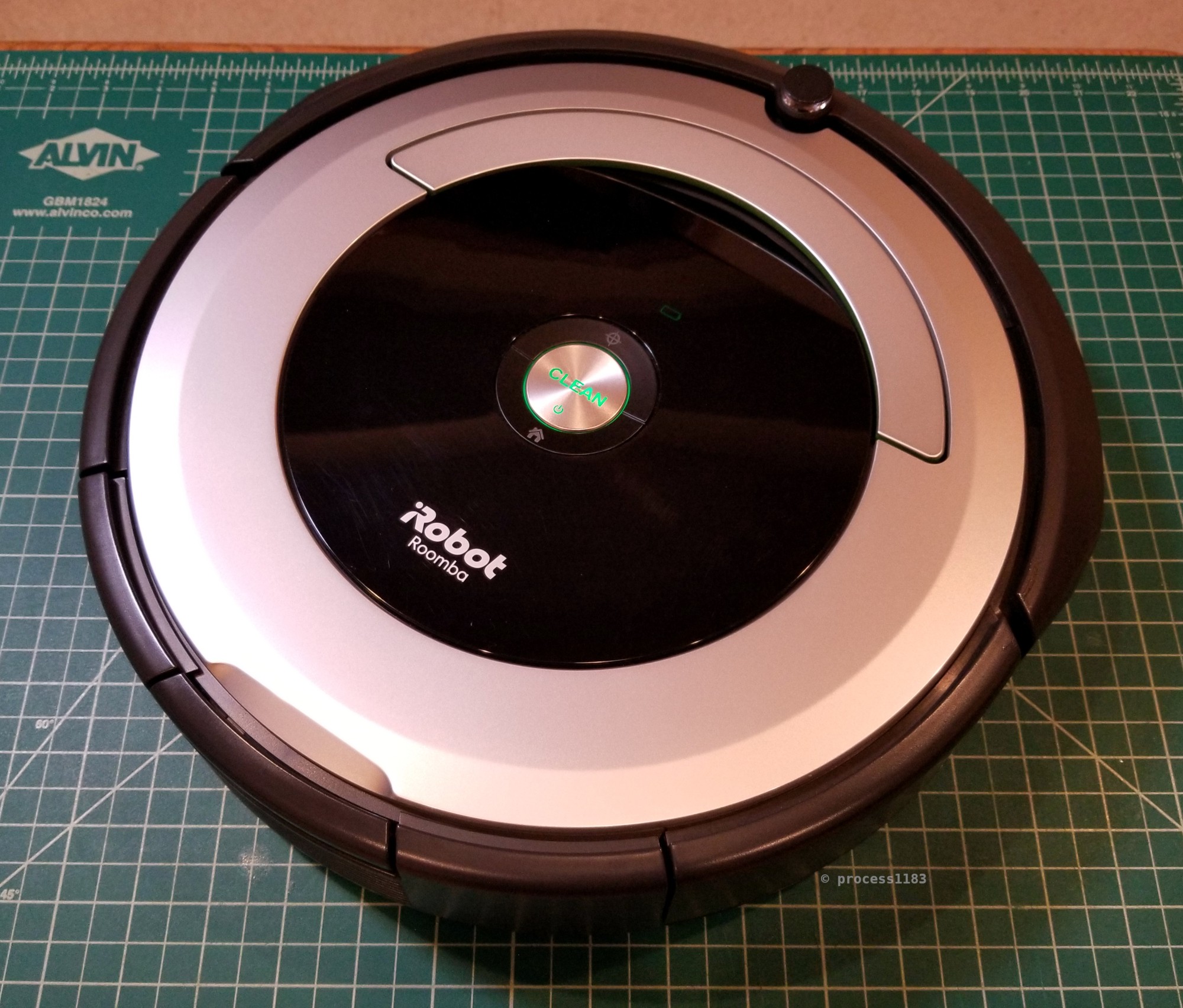
As intended, the completed Roomba with RPi looks no different externally than a stock Roomba 690.
Discussions
Become a Hackaday.io Member
Create an account to leave a comment. Already have an account? Log In.